3 - 28
Electrical parts and motors
Main unit
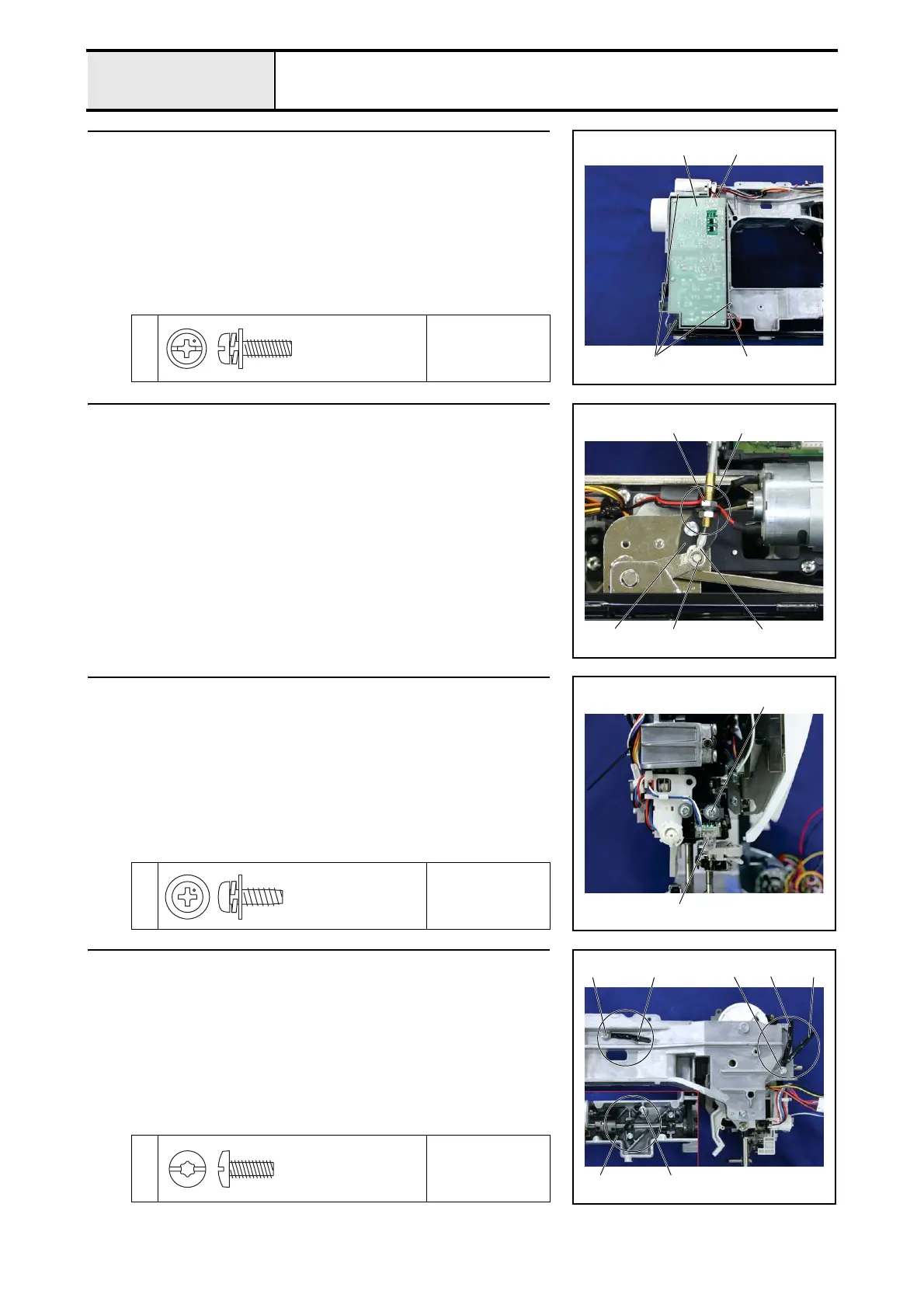
12 Power supply unit F attachment
1. Attach the power supply unit 1 to the arm bed with the 3 screws 1.
2. Connect the inlet assembly lead wirefs connector 2 to the power supply
unit.
3. Connect the main motor assemblyfs connector 3 to the power supply unit.
1
Torque
0.78 – 1.18 N·m
1
3
2
1
Screw, Pan (S/P washer)
M4X14
13 Wire assy. and knee lifter assy. attachment
1. Attach the fitting 1 on the end of the wire assy. (side with two M8 nuts on
it) to the wire holder 2 on the knee lifter assy., and hand tighten the M8
nut 3 on the lower side.
(Fully tighten after 4 - 21"Knee lifter adjustment.")
2. Attach the hook 4 on the end of the wire assy. to the knee lifter assy. shaft,
and attach retaining ring E3.
3
4
Retaining ring E3
1
2
14 PBC unit LED lamp-FL attachment
1. Attach the PBC unit LED lamp-FL 1 to the needle-presser module using
the screw 1.
1
Torque
0.78 – 1.18 N·m
1
1
Taptite,Pan B
M4X12
15 Wire clip attachment
1. Attach the 4 wire clips 1 to 4 with the 3 screws 1.
*Key point
• Secure wire clips 2 and 3 with one screw 1.
1
Torque
1.47 – 1.98 N·m
1
1
4
2
3
1 1
Taptite, Bind S
M4X10
 Loading...