ESM-UM-02782-EN-12
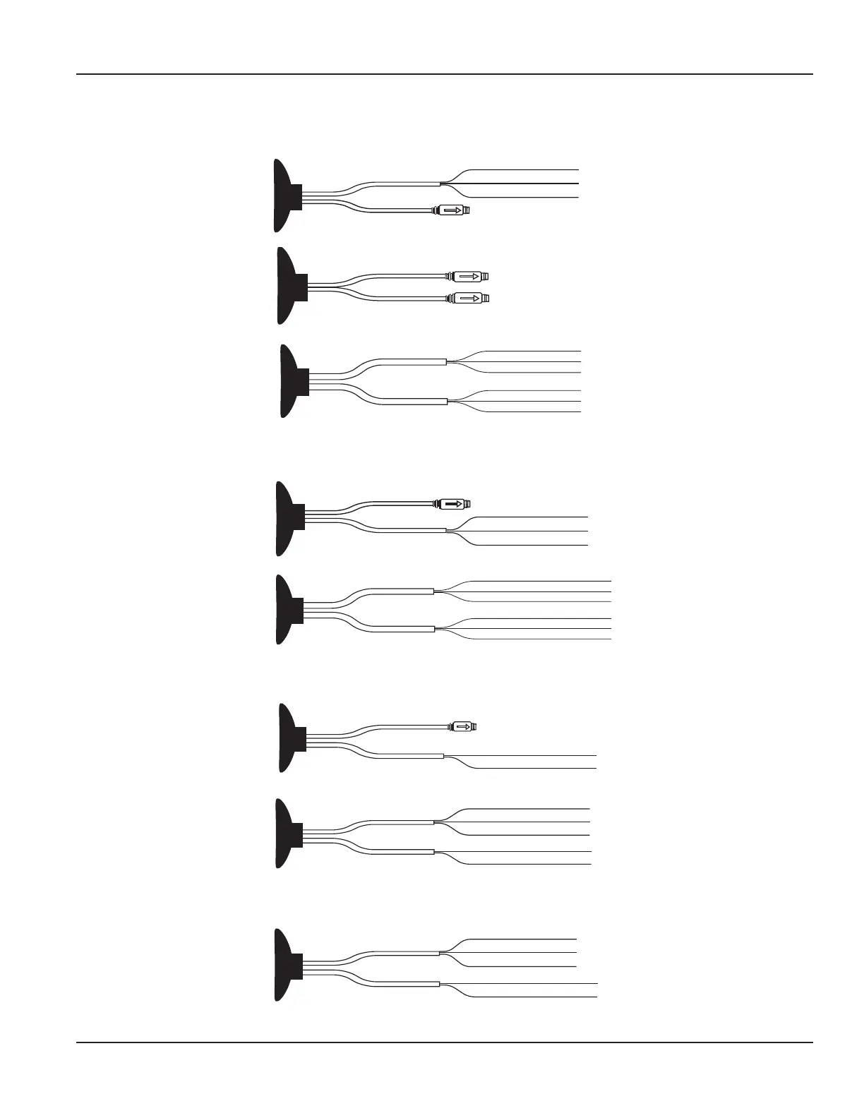
Wiring Connections
Encoder and Encoder
RED - Power
GREEN - Data
BLACK - Ground
Encoder cable with in-line connector
Encoder cable with ying lead
Encoder cable with in-line connector
Encoder cable with in-line connector
RED - Power
GREEN - Data
BLACK - Ground
RED - Power
GREEN - Data
BLACK - Ground
Encoder cable with ying lead
Encoder cable with ying lead
Figure 17: Encoder and encoder wiring options
Encoder and Scaled/Unscaled
RED - Scaled Pulse
GREEN - Unscaled Pulse
BLACK - Ground
Encoder cable with in-line connector
Scaled/unscaled cable with ying lead
RED - Scaled Pulse
GREEN - Unscaled Pulse
BLACK - Ground
RED - Power
GREEN - Data
BLACK - Ground
Encoder cable with ying lead
Scaled/unscaled cable with ying lead
Figure 18: Encoder and scaled/unscaled output wiring options
Encoder and 4-20 mA
4-20 mA cable with ying lead
RED - Loop/External Power +
BLACK - Loop Return/External Power –
Encoder cable with in-line connector
4-20 mA cable with ying lead
GREEN - Data
BLACK - Ground
Encoder cable with ying lead
RED - Loop/External Power +
BLACK - Loop Return/External Power –
Figure 19: Encoder and 4-20 mA wiring options
Scaled/Unscaled and 4-20 mA
4-20 mA cable with ying lead
RED - Scaled Pulse
GREEN - Unscaled Pulse
BLACK - Ground
Scaled/unscaled cable with ying lead
RED - Loop/External Power +
BLACK - Loop Return/External Power –
Figure 20: Scaled/unscaled and 4-20 mA wiring option
Outputs
Page 13 December 2021
 Loading...