ESM-UM-02782-EN-12
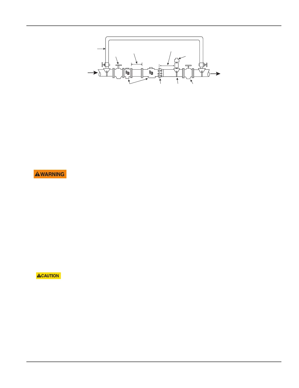
Badger Meter Plate Strainer
and Meter
Coupling
Adaptor
Service
Saddle
Shuto
Valve
Test Tee
Minimum of 5 Diameters
of Straight Pipe
Upstream
Valve
(open)
By-pass
(Permanent or
Temporary)
Upstream
Downstream
Minimum of 5 Pipe Diameters
Downstream of Meter
Figure 4: Recommended meter installation
Installation Instructions
1. Start at this step when cutting in for new service. When cutting in is not required, start at step 2.
• Close the curb (shutoff) valve to relieve water pressure in the line before starting the cutting operation. Provide a
high-quality upstream shutoff valve with a low pressure drop.
• Flush the pipe to clear chips, pipe dope or other plumbing residue.
2. Close the meter inlet-side valve.
3. Open a faucet and wait until water ow stops to depressurize the system. Do not remove the meter until the
ow stops.
DEPRESSURIZE THE LINE BEFORE STARTING ANY DISASSEMBLY OPERATION. REMOVING A METER THAT IS UNDER
LINE PRESSURE CAN RESULT IN COMPONENTS BECOMING PROJECTILES, CAPABLE OF CAUSING PERSONAL INJURY.
4. Check valves and make necessary repairs to the curb (shuto) valve or inlet side valve if necessary.
5. Before installing or removing a meter, close the outlet-side valve to relieve pressure. Protect the area around the meter
against potential spills or leaks that could occur.
6. To replace an existing meter continue with step 7. To install a new meter skip to step 9.
7. Loosen the meter ange bolts and remove the meter and old gaskets.
8. Clean the ange bolts, removing any pipe dope or dirt from the bolts.
9. Check the existing position for proper alignment and spacing. Correct any misalignment or spacing issues.
10. Install the meter in the pipeline in a horizontal or vertical position with the flow arrow on the meter pointing in the
direction of flow. Registration should be upright. With meter and gaskets in place, tighten the ange connection bolts.
Verify the nuts are properly aligned to avoid damage to the anged ends.
11. After the meter is installed, slowly open the inlet shuto valve until the meter is full of water and ensure there are no
leaks. (The more ow you allow through the meter, appropriate for the meter size, the better.)
Take caution when opening the inlet valve to avoid damage to the pressure sensor due to extreme
water hammer.
12. Slowly open the outlet valve until air is out of the meter and service line.
13. Open a service valve downstream of the meter and verify that no foreign debris in the water obstructs the operation
of the system.
14. Check the read on the meter to make sure it is registering a positive number. If it is not, make sure the meter is installed in
the correct direction.
• The meter is shipped in storage mode so that customers do not experience alarms during shipment or installation.
After properly purged of air, and the meter senses a full pipe, it may take up to 30 seconds to begin measurement.
• The meter itself does not require a quantity of flow to begin measurement. The meter just requires that the pipe is
cleared of air and filled with water. If the customer is attempting to purge the meter at low flow rates, it would likely
be more difficult and take longer.
15. When the meter starts recording positive ow, note the reading for your records.
Installation
Page 7 December 2021

 Loading...