WIRING INSTRUCTIONS
Wiring Terminals
1
2
3
6
7
8
Figure 3: Wiring terminals
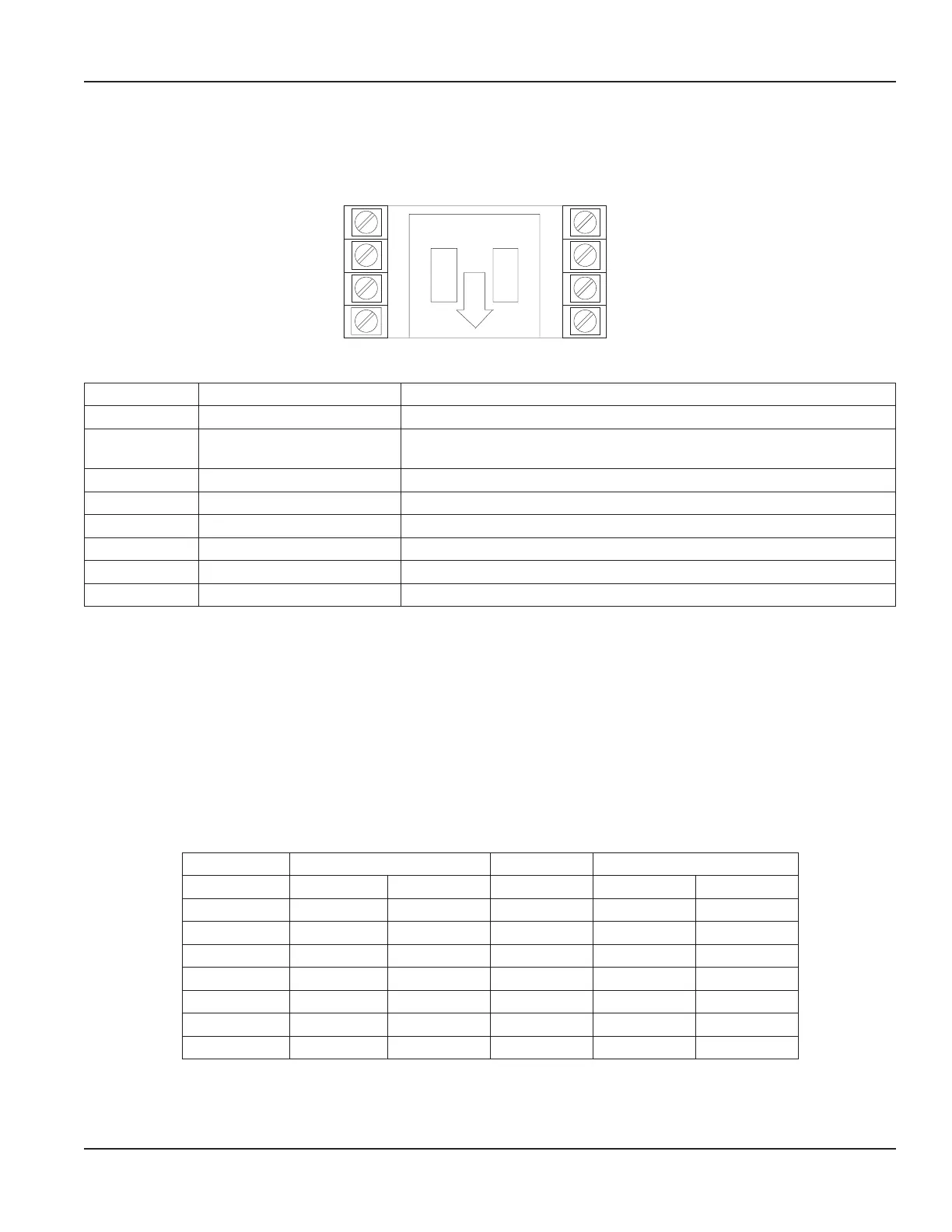
Terminal Function Operation
1 DC common —
2
Count input NPN signal, 280 Hz max or
Dry contact, 95 Hz max
3 — Not used
4 Remote reset
Resets count value when switched to common.
5 Front panel program enable Allows access to program mode when connected to common.
6 Solid-state relay Pulse output (+)
7 Solid-state relay Pulse output (–)
8 DC supply input
10…28V DC for backlighting and/or powering the output.
Table 1: Wiring terminals
Transmitter Connections
For connecting to Badger Meter transmitters, refer to the literature for your specific transmitter and to Table 2 below. The
Connections column refers to the wires on the transmitter. The numbers in parentheses refer to the terminal numbers on the
ER-9. Connect the wire coming from the transmitter to the corresponding terminal number for the ER Remote models.
Connecting to a Generic Reed Switch
To connect a generic reed switch to the ER-9, connect one of the wires to terminal 1 and the remaining wire to terminal 2.
Connecting to a Generic NPN Transmitter
To connect a generic NPN transmitter to the ER-9, connect the emitter to terminal 1. Connect the collector to terminal 2.
Transmitter Connections Transmitter Connections
FT-1 (1/2 in. OP) Black (1) Black (2) PFT-2 White (1) White (2)
FT-1 White (1) White (2) PFT-2E Black (1) Green (2)
FT-1E Black (1) Green (2) PFT-3E Black (1) Green (2)
FT-2 White (1) White (2) PFT-3 White (1) White (2)
FT-420 Black (1) White (2) PFT-420 Black (1) White (2)
MS-E1 Black (1) Red (2) PFT-420/2 Black (1) White (2)
MS-E5 Black (1) Red (2) PFT-4E Term 6 (1) Term 5 (2)
PFT-1E Term 6 (1) Term 5 (2) PM-5 Black (1) Red (2)
Table 2: Transmitter connections
User Manual
Page 7 August 2018 REG-UM-00836-EN-12