BA_375-E42_01_DEF_MJ_4419
11 | 32W. Baelz & Sohn GmbH & Co. · Koepffstrasse 5 · 74076 Heilbronn · Germany · www.baelz.de Seite | Page
Motorized Rotary Actuator baelz 375-E42
5. COMMISSIONING
Comparetheactuatortorqueandthesettravelwiththetechnicalspecicationsofthevalve.
Overloading can lead to serious damage to the valve. Watch out for moving parts during
assembly and adjustment. Risk of injury and substantial material damage.
The rotary actuator is factory set to a rotational travel of 90°.
Actuators with positioners are supplied with a control input signal of 0-10
unless otherwise stipulated upon ordering.
Caution
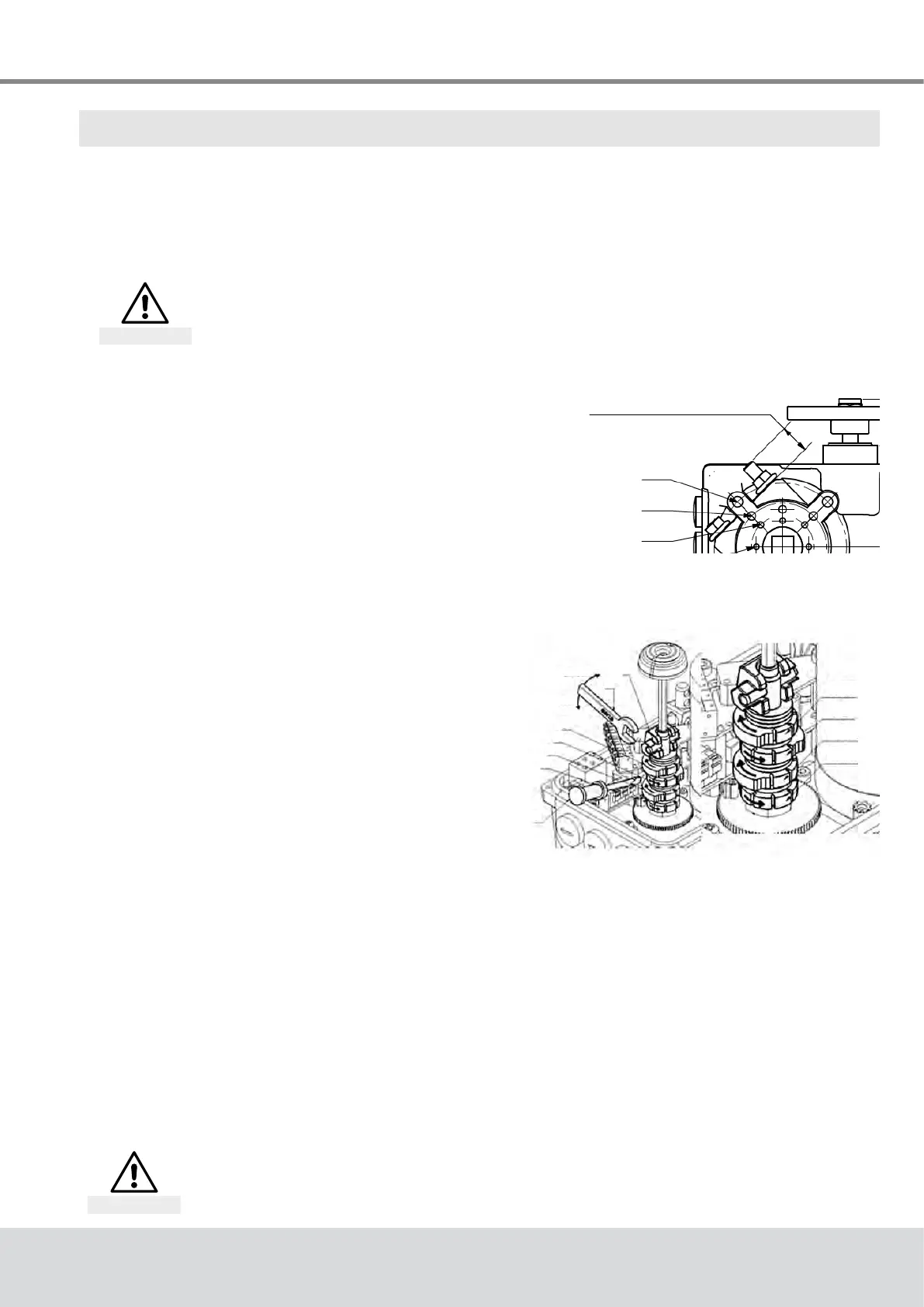
5.1 Setting the mechanical end stops
Move the actuator out of the end position, tighten
the stop screw to the dimension shown in Fig. 3 and
counter-tighten the nut. The stop screw should not
beturnedoutofthespeciedrange.Iftherangeis
exceeded, rotate the coupling by one tooth relative to
the output shaft.
Fig. 3: Setting the mechanical end
stops
5.2 Setting the limit switches
Move actuator into chosen end position. Open the
eccentrictappet(1)usinga10mmwrenchand
adjusttheswitchcamwithascrewdriver(7).Close
theeccentrictappetagainusingthewrench(Fig. 4).
Use of the limit switches to switch off the actuator
will prolong its lifespan.
Fig. 4: Setting the limit switches
5.3 Test run
5.3.1 Checking the direction of rotation
● Adjust the actuator manually to roughly the middle position.
● In direction of travel CLOSE, switch the actuator on and watch the direction of rotation.
● If the direction of rotation is wrong, switch off immediately.
● Checkwiring(jumpers).
● Repeat the test run.
~19mmfor90°
(Min:12,9/Max:25,1)±15°
F05
F07
F10
EZ2
EZ1
WER
WEL
unlock
lock
1
6
2
3
4
5
7
If the direction of travel is set incorrectly, damage to actuator and valve is
imminent as the limit switches will not function with the wrong direction of
rotation!
Attention