BA_375-E42_01_DEF_MJ_4419
13 | 32W. Baelz & Sohn GmbH & Co. · Koepffstrasse 5 · 74076 Heilbronn · Germany · www.baelz.de Seite | Page
1
10
2
3
4
5
6
7
3
8
9
5
1
8
9
7
Motorized Rotary Actuator baelz 375-E42
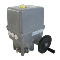
6. RETROFITTING OF ADDITIONAL COMPONENTS
6.1 Retrotting of potentiometer
Disconnect actuator from power supply before starting work!
Danger
1. Remove capacitor bracket.
2. If the actuator is equipped with a heating element, the potentiometer retaining plate [5]
isalreadyttedandcanbeusedforpotentiometerassembly.PutpotentiometerR1[1]
into retaining plate [5] and fasten with a lock washer and nut. Place two locking rings
onthepinion[8]andtthepiniontothepotentiometershaft.Solderthepotentiometer
wiring to the potentiometer, insert downwards through the Ø8 mm hole and connect to
the lower part of the plug connector [2] red-28, gray-29, yellow-30. Fix the lower part of
the plug connector [2] to the potentiometer retaining plate [5] using allen screws M2.5x6
[4].
3. Ifnoheatingelementistted,clipthespacer[9]tothepotentiometerretainingplate
[5]. Replace the allen screw on the gear cover with the spacer bolt M4x22 [7]. Fit the
potentiometer retaining plate [5] into the actuator, clip the spacer [9] into the gear cover
andxtospacerboltM4x22[7]usingallenscrewM4x6.Toeliminatebacklash,gently
push the potentiometer assembly in the direction of the camshaft whilst tightening the
screw.Insertthecapacitorbracketintotheretainingplate[5]andxwithallenscrew
M4x6.
Fig. 5: Fitting the potentiometer
2 x locking ring