BA_375-E42_01_DEF_MJ_4419
19 | 32W. Baelz & Sohn GmbH & Co. · Koepffstrasse 5 · 74076 Heilbronn · Germany · www.baelz.de Seite | Page
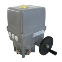
Motorized Rotary Actuator baelz 375-E42
7.2.4 Normal and safety modes
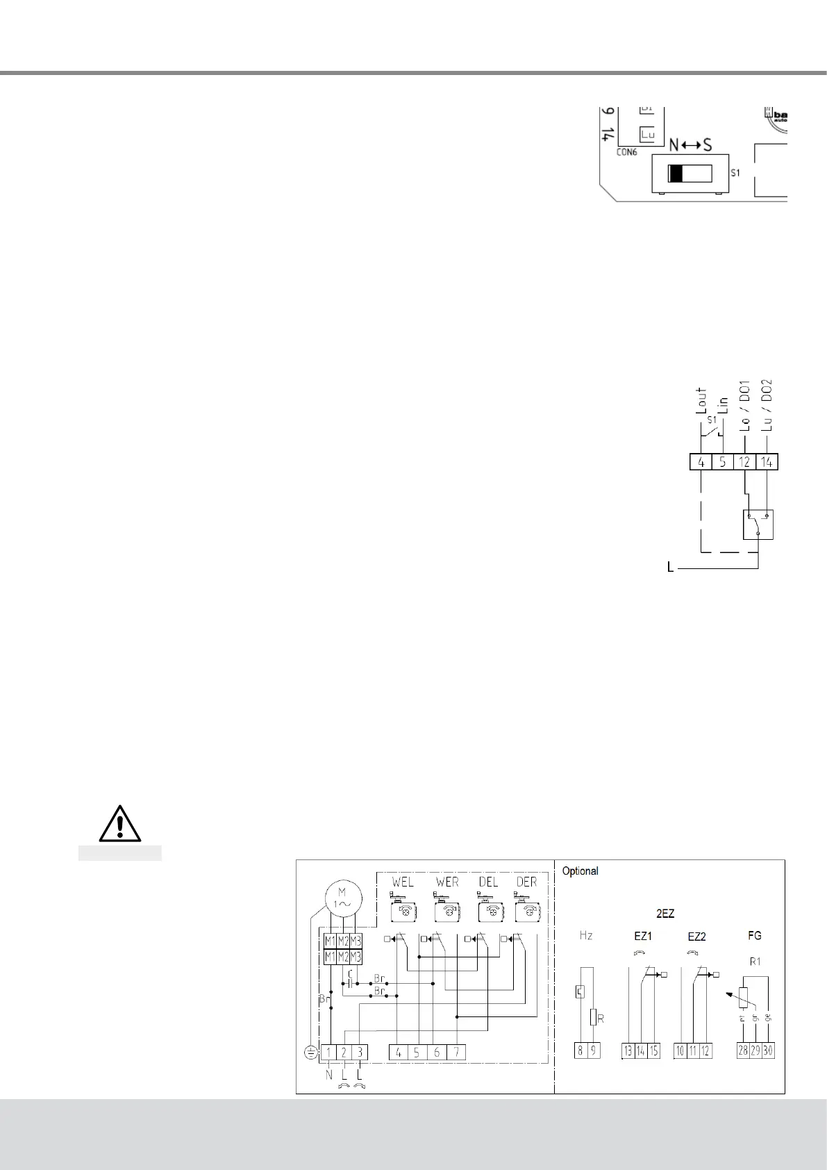
In normal mode the position of the valve is controlled by the set
valueatanalogueinputAI2.TheN↔Sswitchshowninthepicture
ontherightissettonormalmode(N).Innormalmode,noexternal
control systems can be connected to terminals 12 and 14.
7.2.5 Safety mode: freeze protection and excessive temperature
Insafetymodetheactuatorcanbesenttoasafeposition(extended/retracted,dependingon
thedirectionofactionofthevalve)incaseoffailureormalfunctioningofthemicrocontroller.
To operate the Baelz 7020 in connection with an external freeze protection and/or excessive
temperaturethermostat,settheN↔Sswitchtosafetymode(S).
Connect the freeze protection and/or excessive temperature thermostat according to desired
function and priority. Be sure to take the direction of action into account! See wiring diagrams
in the baelz 7020 operating instructions.
7.2.6 3-point control with a continuous output signal
1. Set the positioner up and wire to power supply as described
previously and initialize as described in section 7.5.2.
2. To deactivate the error signal, if desired, set the DIP-switch 11 to 1
("ON")andchangethefollowingvaluesinthemenuitem"CA"using
WinBasTools(onPC,seebaelz7020operatinginstructions):
● AD to 0
● EFP to 0.0%
● LA to 1
(Ifyoudon'tmindtheredLEDerrorsignal,step2canbeleftout
completely.Thishasnoeffectonthefunctionofthepositioner.)
3. SettheN↔Sswitch(Fig. 7)to"S"andwireasshowninFig. 8(thepositionermust
remainconnectedtothepowersupplythroughout).
4. The required signal can now be picked up on AO1 and AO2.
IMPORTANT NOTE: Before any further re-initialization of the device, disconnect terminals 12
and14andsettheN↔Sswitchtonormaloperation(N).
7.3 Wiring diagrams and allocation of connection terminals
Disconnect actuator from power supply before starting work
See also section 4.4.
Danger
7.3.1 Wiring diagram
Fig. 7: N↔S-switch
Fig. 8: Wiring diagram
3-point-signal
Fig. 9: Wiring diagram
basic actuator