8 | 32W. Baelz & Sohn GmbH & Co. · Koepffstrasse 5 · 74076 Heilbronn · Germany · www.baelz.de Seite | Page
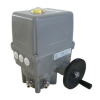
Motorized Rotary Actuator baelz 375-E42
4. ASSEMBLY
Make sure that the specications on the nameplate correspond to those in
the order documents!
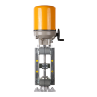
4.1 Fitting position
Do not mount rotary actuators "head down" below the valve. Allow for about 200 mm space
above the cover at the site of installation.
4.2 Assembly with the valve
Before assembly, check the rotary actuator for damage. Damaged parts should be replaced
with original spare parts. After assembly, check the rotary actuator for damage to the paint.
Touch up the paint if necessary in order to prevent corrosion.
ForgatevalvestherecommendedassemblypositionistheSHUTendposition.Forthis,
turnthecrankwheelontherotaryactuatorclockwiseuntilthemechanicalstopoftheSHUT
position is reached before assembling.
For ball valves the recommended assembly position is the OPEN end position. For this, turn
the crank wheel on the rotary actuator anticlockwise until the mechanical stop of the OPEN
position is reached before assembling.
Thorouglydegreasethecontactsurfacesoftheconnectingangesoftherotaryactuator
and the valve. Lightly grease the valve shaft. Fit the coupling to the valve shaft and secure it,
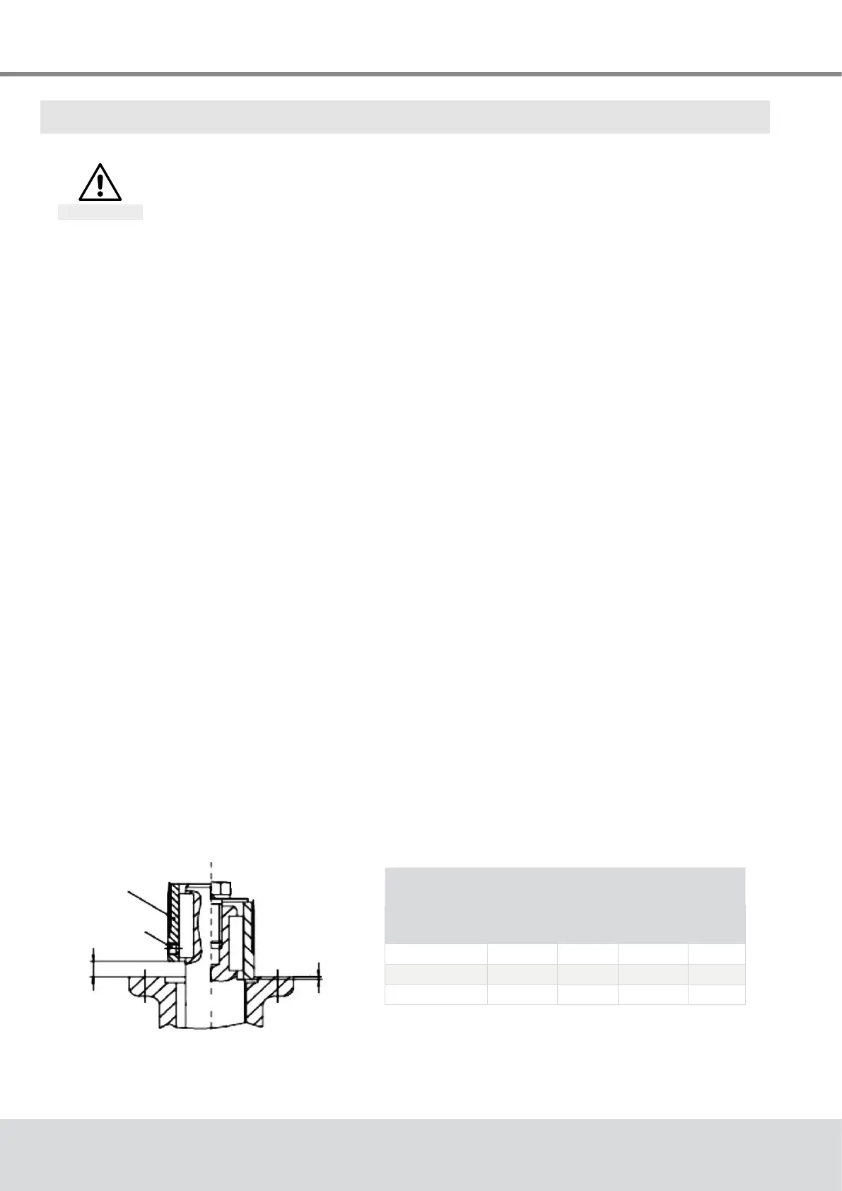
keepingtothedimensionsXandY(seeFig. 2 and Table 3,below).
Lubricate gear teeth on the coupling thoroughly with acid-free grease. Fit the actuator so
thattheconnectionholesintheactuatorandthevalveangearealigned,possiblyturning
the actuator on the coupling by one tooth. If necessary, turn the crank wheel slightly towards
OPENorSHUTuntiltheholesarealigned.Ensurecorrectalignment(ifapplicable)and
completecontactofthemountingfaces.Fixactuatorwithscrews(atleastquality8.8)and
spring washers; Tighten screws alternately and gradually up to the torque given in Table 3,
below.
Fig. 2: Coupling / Assembly of actuator and valve
Attention
Table 3. Dimensions for coupling and
tightening torques for screws
Connection
X max.
(mm)
Y max.
(mm)
size
T
A
(Nm)
F05 0,5 3 4 x M6 10
F07 0,5 3 4 x M8 25
F10 0,5 3 4 x M10 50
coupling
grub screw
valve
A B
Y
X