BA_375-E42_01_DEF_MJ_4419
23 | 32W. Baelz & Sohn GmbH & Co. · Koepffstrasse 5 · 74076 Heilbronn · Germany · www.baelz.de Seite | Page
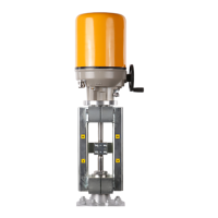
Motorized Rotary Actuator baelz 375-E42
DIP10:
An actuator characteristic can be used indirectly to change a valve characteristic. If, for
example, the valve has an equal percentage characteristic, an inverse equal percentage
actuator characteristic can be used to generate a resulting linear characteristic, see illustration
below.
Theactuatorcharacteristic(DIP10)canalsobecombinedwiththecharacteristicswhich
canbeselectedusingDIPs7,8and9(e.g.splitrange).Themicrocontrollerrstprocesses
thecharacteristicdenedbyDIPs7,8and9andsubsequentlythecharacteristicdenedby
DIP 10.
In Modbus mode, two further actuator characteristics can be selected: equal percentage and
quadratic inverse equal percentage.
DIP11:
DIPswitch11denesthemodeofoperation:1=Modbusmode,0=standardmode.
Standardmodeisusedtoapplypredenednormalsettings.
DIP12:
Starts an initialization run when switched from 0 to 1. If DIP 12 is left in position 1 when the
7020A positioner is switched on, an initialization run will not be startet.
As long as DIP 12 is set to 1, errors and alarms occurring during normal positioner operation
will not be shown. This enables errors occurring during initialization to be distinguished from
errors during normal positioner operation. Switch DIP 12 back to 0 after the initialization run
(afterhavinganalysedpossibleerrorcodes)toshowanyerrorsoccurringinnormalpositioner
operation on the red LED. See also section 7.5.2 "Initialization run".
shut
valve 2, offset 50 % [0 1 0]*
valve 1, offset 0 % [1 0 0]*
valve 1, offset 0 % [1 1 0]*
valve 2, offset 33,3 % [0 0 1]*
valve 1, offset 66,6 % [1 0 1]*
input signal
valve position
open
shut
0 % 100 %
50 %
33,3 %
66,6, %
100 %
0 %
100 %
0 %
shut
shut
open open
shut
open
open
0 % 100 %
0 %
100 %
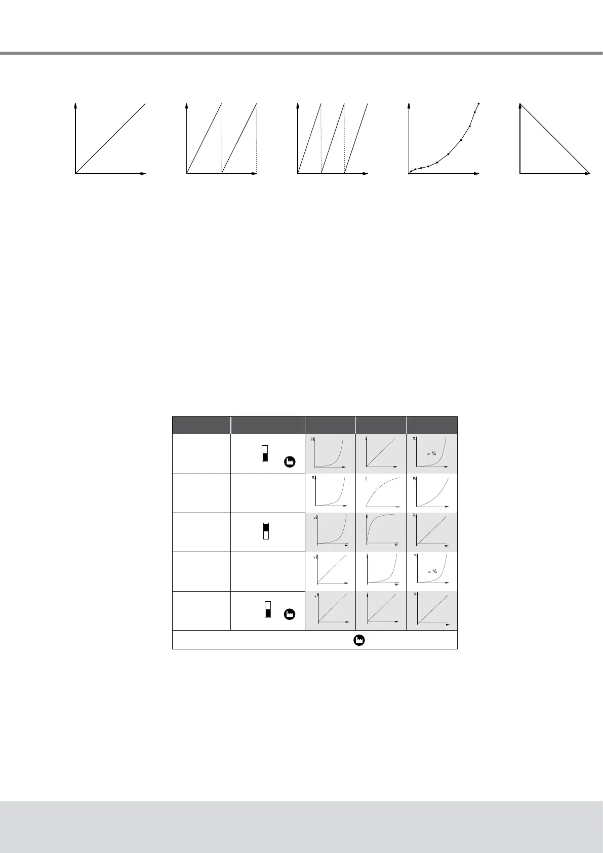
Split range
split 50 %
Linear
Split range
split 33 %
11-point
characteristic
Inverse linear
[0 0 0]
[0 1 1]* [1 1 1]*
Fig. 12: Graphical illustration of selection of functions by DIP switches 7, 8 & 9
1
Desired
characteristic
Equal percentage
Quadratic
Linear
Equal percentage
Linear
DIP-switch 10
Characteristic of the
valve
Characteristic of the
actuator
Effective at valve
= factory setting
Travel
Travel
Travel
Travel
Travel
Signal
Signal
Signal
Signal
Signal
Signal
Signal
Signal
Signal
Signal
TravelTravelTravelTravel
Travel
1
0
10
0
10
1
0
10
actuator characteristic
only selectable in
Modbus mode
actuator characteristic
only selectable in
Modbus mode