USER MANUAL – M625/M325 DRIVE SYSTEM
9
INSTALLATION
5. Tighten the hose clamp on the frame with
a cross screwdriver (Note: the hoop should
be tied on the rubber washer, and the
hoop is perpendicular to the down tube.
The locking torque is 3-4Nm), and then
tighten the unlocked parts of step 2 (the
locking torque is 9-10Nm)and step 3 (the
locking torque is 50-60Nm).
Hose clamp
A
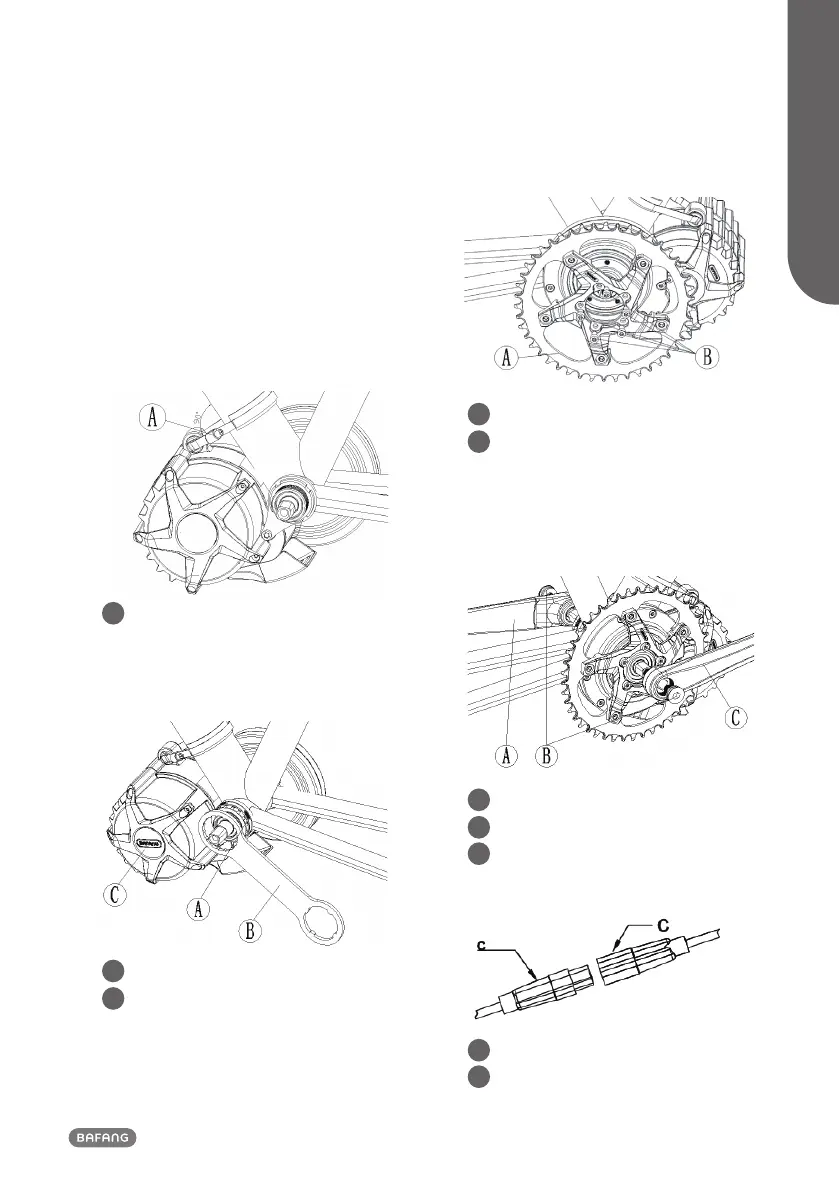
6. With the special tool tighten the locking
ring M33-PH1(B) onto the motor (the
locking torque is 25-30Nm).
Locking ring M33-PH1(B)
Special tool
A
B
7. Put the chainset on the output end of the
motor, and then with five M5 star screws
tighten it on the motor (the locking torque
is 25-30Nm).
Chainset
M5 Internal star screw
A
B
8. Mount the right crank on the right shaft
and with an M8 inner hex screw tighten it,
the locking torque is 35-40Nm, tighten the
left crank in the same way.
Left crank
M8 Internal hex screw
Right crank
A
B
C
9. Connect the EB-BUS cable
Female connector of EB-BUS
Male connector EB-BUS from drive unit
C
c