USER MANUAL – M625/M325 DRIVE SYSTEM
6
6 INSTALLATION
The bicycle adapted to the M625/M325 drive system needs to meet the following
requirements:
• The upper area of downtube shall have a motion range of 390mm in length and 170mm in height
for battery installation.
• Cable brake is adopted for the sake of modification of e-brake lever.
• The length of bottom bracket matches the length of motor shaft.
• The CL value of chainring shall be compatible to that of the original bicycle.
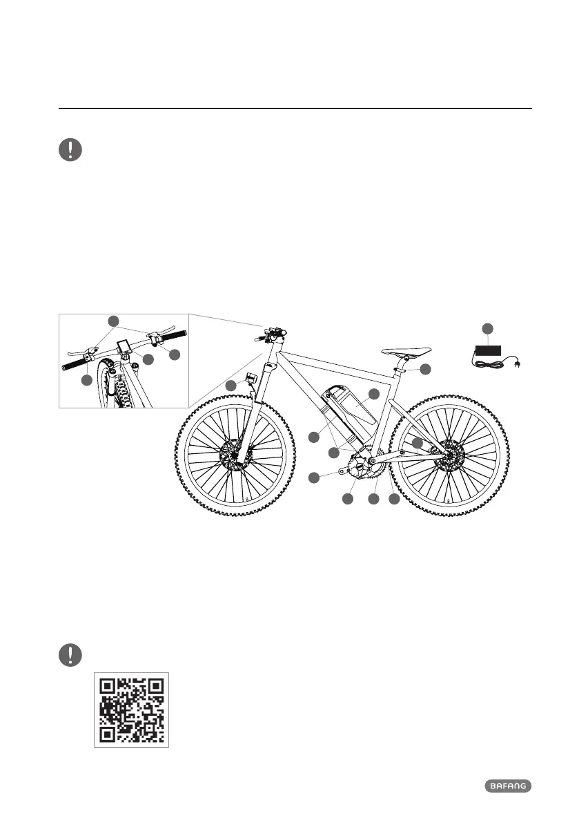
6.1 Summary of the Components
3
4
15
14
11
1
12 13
5
2
10
9
6
7
8
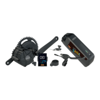
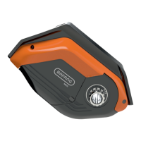
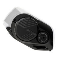
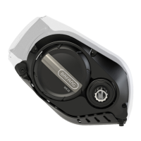
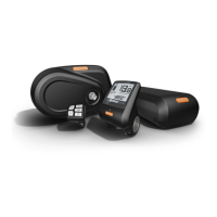
1. Drive Unit 2. Speed Sensor 3. Battery 4. Battery Slide Rail
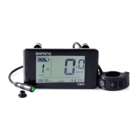
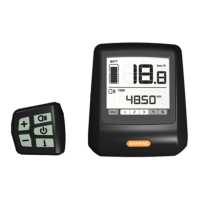
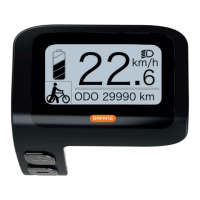
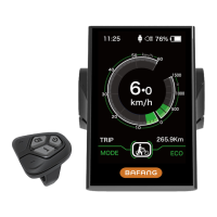
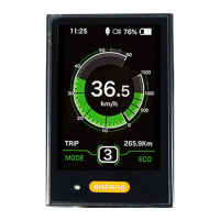
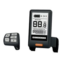
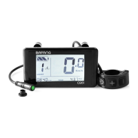
5. 4A Charger 6. Display 7. Control Panel 8. e-Brake Lever
9. Throttle 10. Headlight 11. Taillight 12. Chainring
13. Crank (left) 14. Crank (right) 15. Hoop
You can scan the QR code to watch the installation video of DIY system.