INTRODUCTION
WBPEEUI240755B0 2 - 1
SECTION 2 - DESCRIPTION AND OPERATION
INTRODUCTION
This section explains the inputs, outputs, logic power and con-
nections for the IMCIS12 and IMQRS12 modules. The CIS and
QRS modules are process field I/O interfaces for a multi-func-
tion processor (MFP) module. The I/O module circuitry per-
forms the following functions:
•
Analog to digital (A/D) conversion. It changes analog
inputs to digital values the MFP can process.
•
Digital to analog (D/A) conversion. It changes the MFP dig-
ital values to analog voltage or current signals to control
process field devices.
•
Accepts digital field inputs and isolates the module cir-
cuitry from the process.
•
Outputs digital signals to process field devices and isolates
the module circuitry from the process.
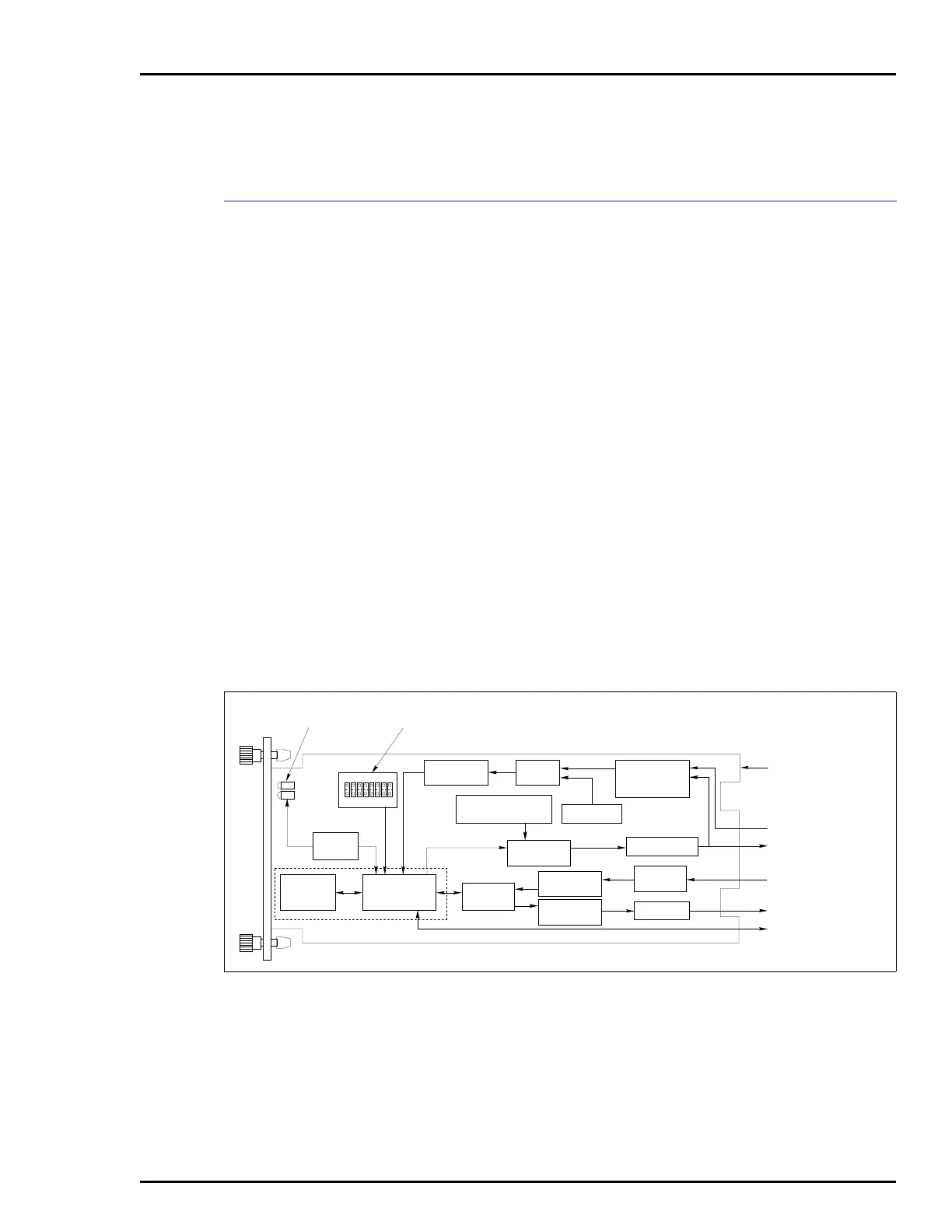
The MFP communicates with its I/O modules on a parallel I/O
expander bus as shown in Figure 1-1. It references the address
set by I/O address dipswitch (S1). Figure 2-1 is a block dia-
gram of the CIS and QRS modules.
Figure 2-1. Block Diagram
18
OPEN
LOGIC POWER
DIGITAL INPUTS
ANALOG INPUTS
DIGITAL OUTPUTS
ANALOG OUTPUTS
I/O EXPANDER
BUS
T00084A
DIGITAL I/O
BUFFER
A/D
CONVERTER
INPUT
SELECT
INPUT
CONDITIONING
JUMPERS
I/O EXPANDER
BUS
INTERFACE
BUS FAULT
DETECTOR
MODULE
STATUS
THRESHOLD
DETECTION
D/A
CONVERTER
E/I JUMPERS
REFERENCE
OUTPUT
ISOLATION
INPUT
ISOLATION
DRIVER
P2
P3
P1
S1
ADDRESS
SWITCH
MODULE
STATUS LEDS
ANALOG OUTPUT
DEFAULT JUMPERS