DESCRIPTION AND OPERATION
I/O CIRCUIT CONNECTIONS
WBPEEUI240755B0 2 - 5
I/O CIRCUIT CONNECTIONS
The I/O signals connect to the 30-pin card edge connector P3 of
the CIS and QRS modules using a termination cable from a ter-
mination unit (TU) or termination module (TM). It also supplies
+24 VDC power to operate the analog output circuits.
I/O EXPANDER BUS
The INFI 90 OPEN I/O expander bus is a high speed synchro-
nous parallel bus. It provides a communication path between
control modules and I/O modules. The control module pro-
vides the control functions and the I/O module provides the
input/output functions to and from the control module. The
P2 card edge connector of the I/O module and control module
connect to the bus.
The I/O expander bus is parallel signal lines located on the
module mounting unit (MMU) backplane. A 12-position dip-
shunt placed in a connection socket on the MMU backplane
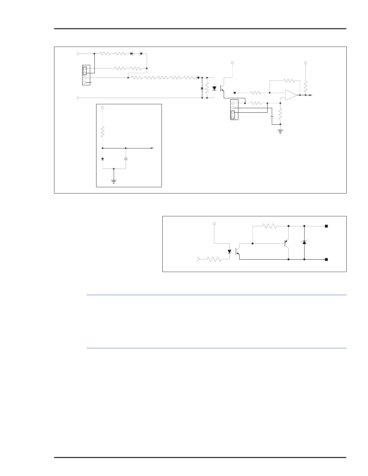
Figure 2-4. Digital Input Circuit Example
FIELD
INPUT
J1
1
2
3
4
1
2
3
J2
4
T00324A
1 4
2 3
PWR PWR
REF DI
+
–
10
13
11
TO INPUT
CIRCUITRY
PWR
REF DI
DI REFERENCE
Figure 2-5. Digital Output Circuit Example
FROM
OUTPUT
CIRCUITRY
FIELD
OUTPUT
TP00085A
POWER
14
23