INSTALLATION
SETUP/PHYSICAL INSTALLATION
WBPEEUI240755B0 3 - 5
Analog Output Mode Jumpers (J9, J11, J13, J15)
The analog output mode jumpers select the mode of each ana-
log output. The mode can be set to current (four to 20 milliam-
peres) or voltage (one to five VDC). Refer to Figure 3-1 for
location of jumpers and Table 3-3 for jumper settings.
Analog Input Mode Jumpers (J17, J18, J19, J20)
The analog input mode jumpers select the mode of each analog
input. The mode can be set to current (four to 20 milliamperes)
or voltage (one to five VDC) either differential voltage or sin-
gle-ended voltage mode.
Selection of the analog input mode can be made at the termi-
nation unit or at the module. Use one of the following proce-
dures.
1. At the module, set the analog input jumpers (J17, J18, J19
and J20) to the differential voltage mode shown in Table 3-4
(jumpers removed). Select the desired analog input dipshunt
configuration at the termination unit. Refer to Appendix A and
Appendix B.
2. At the termination unit, use the dipshunt configuration for
differential voltage mode. For the NTCS04 TU, refer to
Appendix A. For the NICS01 TU, refer to Appendix B. Set the
analog input jumpers (J17, J18, J19, and J20) on the module
to the proper analog input desired. Refer to Table 3-4 for
jumper settings. Refer to Figure 3-1 for location of jumpers.
Table 3-2. Analog Output Default Jumpers
Analog
Output
Time-Out Option Power-Up State
Jumper
Go To
Power-Up
Hold Jumper 0% 100%
1 J82-31-2J72-31-2
2 J14 2-3 1-2 J12 2-3 1-2
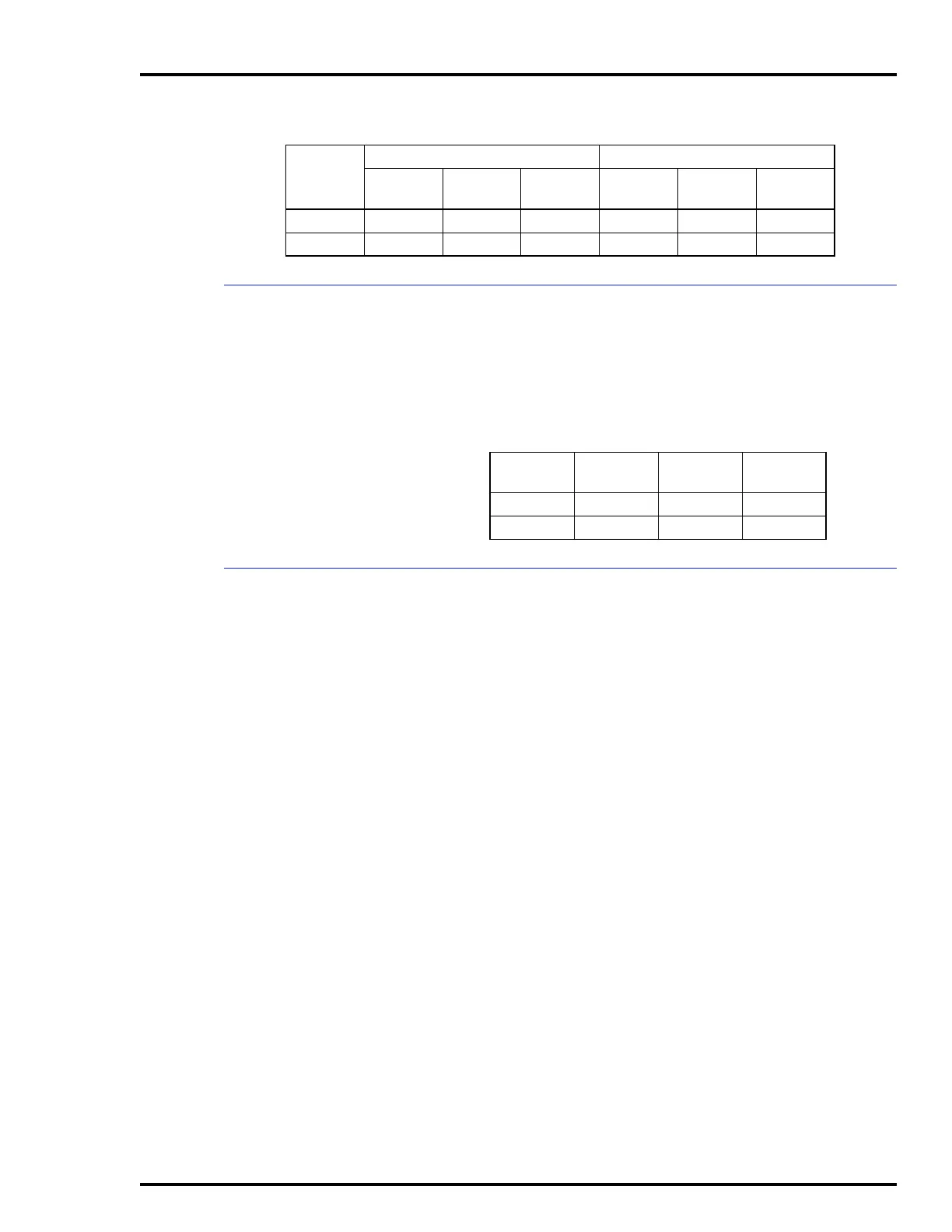
Table 3-3. Analog Output Mode Jumpers
Analog
Output
Jumper
Current
Mode
Voltage
Mode
1 J9, J11 2-3 1-2
2 J13, J15 2-3 1-2