INTRODUCTION
WBPEEUI240755B0 A - 1
APPENDIX A - TERMINATION UNIT (NTCS04)
CONFIGURATION
INTRODUCTION
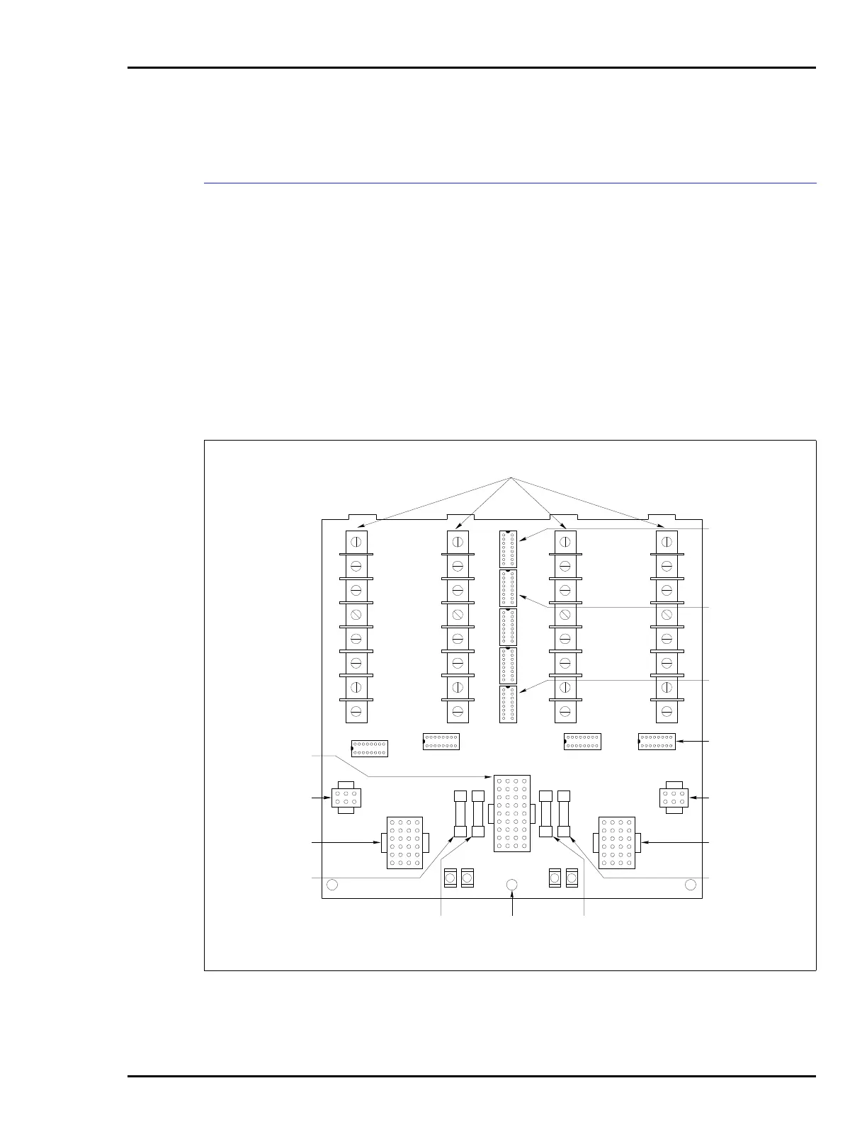
The IMCIS12 and IMQRS12 modules can use an NTCS04 for
termination. The termination unit can handle four analog
inputs, two analog outputs, three digital inputs and four digital
outputs. Dipshunts on the termination unit configure the I/O.
NOTE:
There is no dipshunt socket to configure for the digital out-
puts on the NTCS04.
Figures A-1 shows the NTCS04 configuration sockets (dip-
shunts). Refer to this figure when connecting field wiring to the
NTCS04 termination unit. Refer to Tables A-1 through A-4 to
determine the dipshunt strapping.
Figure A-1. NTCS04 Termination Unit Layout
T00101A
F2F3 F1F4
E3 E2E4 E1
F2
P3 P2
P4P5
P1
TB4 TB2
8
6
5
4
3
2
1
7
8
6
5
4
3
2
1
7
8
6
5
4
3
2
1
7
8
6
5
4
3
2
1
7
TB1TB3
XU9
XU8
XU6
XU5
XU7
XU4
XU3 XU2 XU1
ANALOG INPUT
CONFIGURATION
SOCKETS
(XU1-XU4)
DIGITAL INPUT
CONFIGURATION
SOCKETS
(XU5-XU7)
ANALOG
OUTPUT
CONFIGURATION
SOCKET (XU9)
FIELD I/O TERMINATION BLOCKS
(TB1-TB4)
STATION
ANALOG INPUT
FEEDBACK
CONFIGURATION
SOCKET (XU8)
SERIAL LINK
CONNECTOR
(P4)
STATIONS
CONNECTOR
(P2)
STATIONS FUSE
CLIP (F1)
SERIAL LINK
CONNECTOR
(P5)
MODULE CABLE
CONNECTOR (P1)
CHASSIS
COMMON
DIGITAL
INPUTS FUSE
CLIP (F4)
AUX. +24 V
FUSE CLIP
(F2)
STATIONS
CONNECTOR
(P3)
STATIONS FUSE
CLIP (F3)