TROUBLESHOOTING
MODULE PIN CONNECTIONS
WBPEEUI240755B0 5 - 3
2. Modify the address in the MFP configuration (FC 79 specifi-
cation S1) to correspond with the address set on switch S1.
Use an INFI 90 OPEN operator interface to modify the configu-
ration (for procedures on how to modify a function code specifi-
cation, refer to the appropriate instruction manual for the
operator interface you are using).
The MFP generates a MISSING SLAVE MODULE ERROR if the
I/O expander bus is not connected between it and the I/O
module. Verify the bus connection on the MMU backplane.
If you determine the I/O module is faulty, replace it with a new
one. Refer to Section 7 for procedures to replace an I/O mod-
ule.
MODULE PIN CONNECTIONS
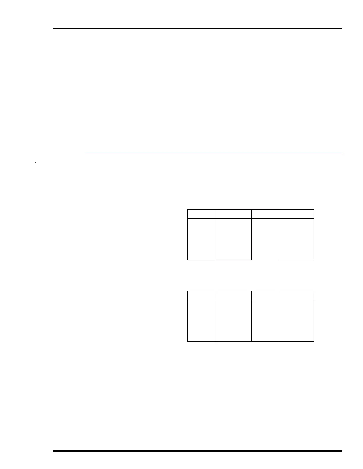
The I/O module has three connection points for external sig-
nals and power (P1, P2 and P3). Tables 5-2, 5-3 and 5-4 show
the pin connections.
Table 5-2. P1 Power Pin Connections
Pin (P1) Connection Pin (P1) Connection
1
2
3
4
5
6
+5 VDC
+5 VDC
NC
NC
Common
Common
7
8
9
10
11
12
+15 VDC
-15 VDC
PFI
PFI
NC
NC
NC = Not Connected
PFI = Power Fail Interrupt
Table 5-3. P2 Expander Bus Connections
Pin (P2) Signal Pin (P2) Signal
1
2
3
4
5
6
Data 1
Data 0
Data 3
Data 2
Data 5
Data 4
7
8
9
10
11
12
Data 7
Data 6
Clock
Sync
NC
NC
NC = Not Connected