DESCRIPTION AND OPERATION
ANALOG I/O
2 - 2 WBPEEUI240755B0
®
ANALOG I/O
The CIS and QRS modules can input four separate analog sig-
nals configurable as voltage (one to five VDC) single ended or
differential, or current (four to 20 milliamperes) field powered.
It allows for a common mode (inputs change together propor-
tionally) differential voltage of ±10 VDC. The I/O module out-
put mode is selectable: current or voltage.
Analog Inputs
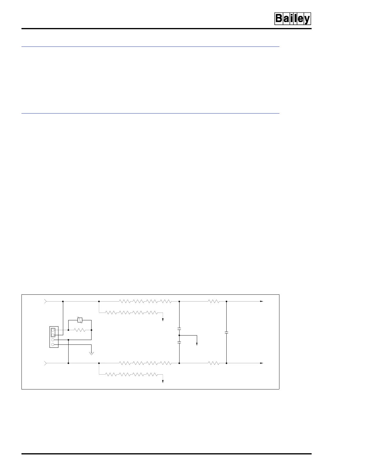
The input conditioning block consists of two pole input filters
that reduce input signal noise (Fig. 2-2). Refer to Table 1-5 for
normal mode rejection (differential change) and common mode
rejection specifications for the differential inputs. The input
conditioning block consists of an I/E conversion resistor and a
configuration jumper (for each channel) to configure the I/O
module to input current or voltage (single ended or differen-
tial).
The input select block consists of an analog multiplexer and
an inverting difference amplifier. The multiplexer selects one of
the four inputs or the reference block inputs (calibration volt-
ages). The difference amplifier converts the selected input to a
single ended signal.
The A/D converter block circuit changes the input signal to a
12-bit value that is sent to the I/O expander bus interface.
This value is an analog count that corresponds to the input
voltage. Nominal input range is 1 to 5 VDC (4 to 20 milliamps);
however, it allows for a 0.75 to 5.25 VDC (3 to 21 milliamp)
input range which is ±6.25 percent of the nominal input range
span (4 VDC).
Figure 2-2. Analog Input Circuit Example
FIELD
INPUT
J17
1
2
3
4
T00325A
TO INPUT
SELECT
BLOCK