INTRODUCTION
WBPEEUI240755B0 C - 1
APPENDIX C - QUICK REFERENCE
INTRODUCTION
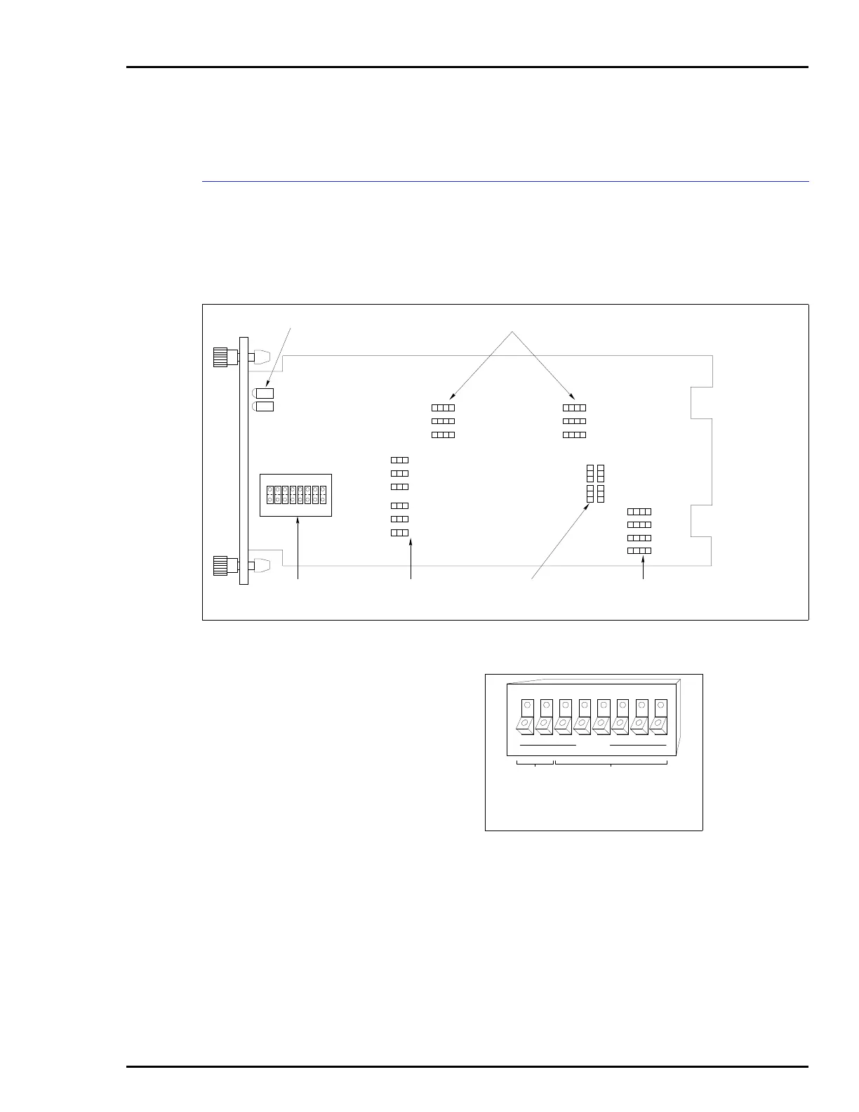
This section provides a source for reference information. It
contains the jumper and switch locations for the IMCIS12 and
IMQRS12 modules. Refer to Section 3 for a complete descrip-
tion of jumper and switch settings.
Figure C-1. Switch and Jumper Locations
ANALOG OUTPUT
DEFAULT JUMPERS
ANALOG INPUT
MODE JUMPERS
ANALOG OUTPUT
MODE JUMPERS
ADDRESS
SWITCH
EDGE
CONNECTORS
P1
P3
P2
MODULE STATUS LEDS DIGITAL INPUT JUMPERS
S1
18
OPEN
T00086A
1
J1
J3
J5
1
1
1
J7
J9
J17
J15
J20
J12
J8
J11
J18
J14
J10
J13
J19
J16
1
J2
J4
J6
Figure C-2. Address Select
Switch (S1)
1 2 3 4 5 86 7
OPEN
MUST
REMAIN
CLOSED
I/O
ADDRESS
MSB LSB
TP65205B
NOTE: OPEN POSITION = LOGIC 1