INTRODUCTION
WBPEEUI240755B0 4 - 1
SECTION 4 - OPERATING PROCEDURES
INTRODUCTION
This section explains the front panel indicator and start-up
procedures for the IMCIS12 and IMQRS12 modules.
MODULE STATUS INDICATOR
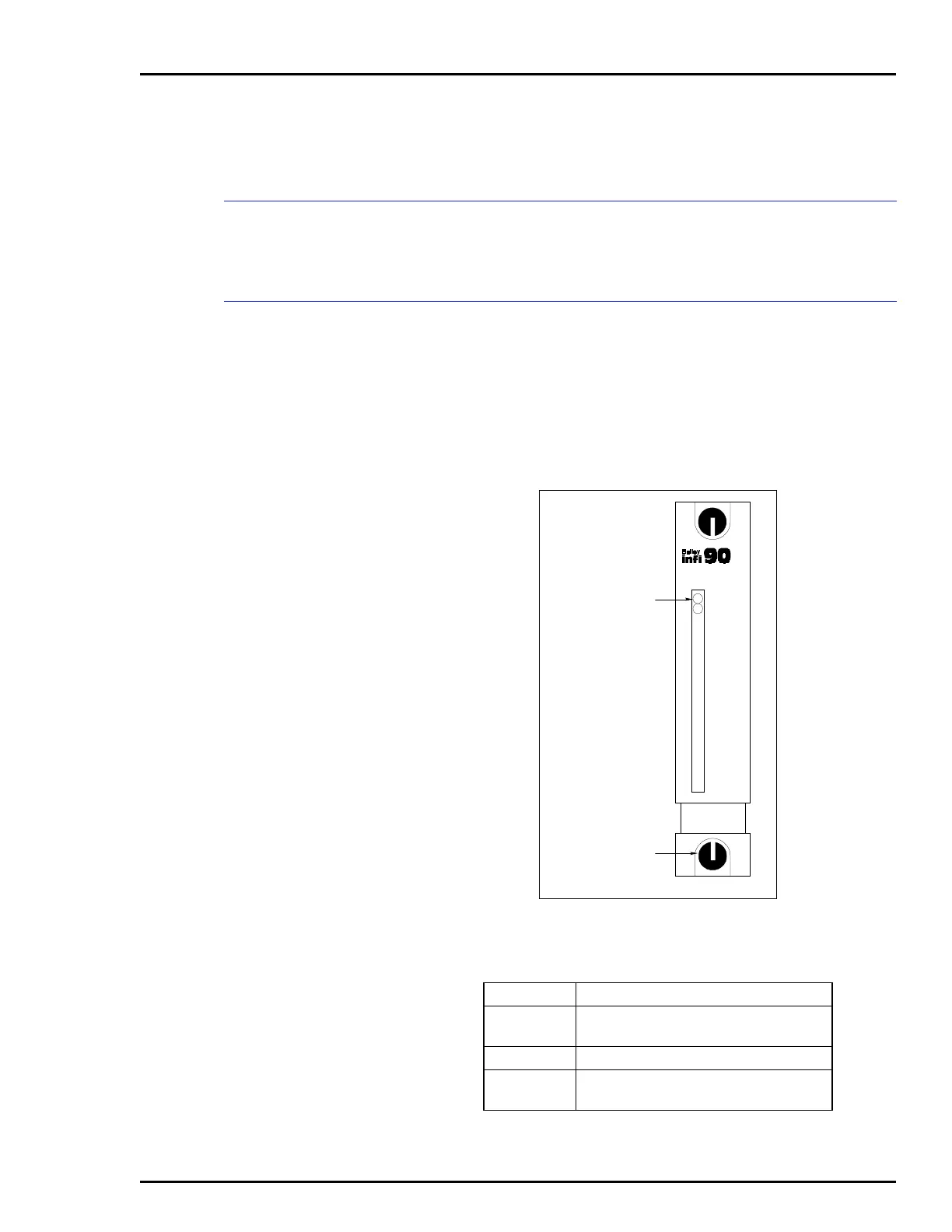
The CIS and QRS modules have two (red/green) LEDs visible
through the module front panel. When lit, the green LED indi-
cates a good I/O module status. If the LED is red, it indicates a
bad I/O module status. The location of the LED indicators is
shown in Figure 4-1. Table 4-1 explains the three states of the
status LED indicators. Refer to Section 5 to determine correc-
tive actions.
Figure 4-1. Front Panel Indicators
Table 4-1. Status LED Indicator
LED Indication
Solid green
(POWER)
Enabled and communicating with MFP
Off No power or not enabled
Solid red
(FAIL)
Bus fault timer error (time-out)
MODULE STATUS
LATCHED
POSITION
T00088A
IMCIS12
FAIL
POWER