TERMINATION UNIT (NTCS04) CONFIGURATION
INTRODUCTION
WBPEEUI240755B0 A - 3
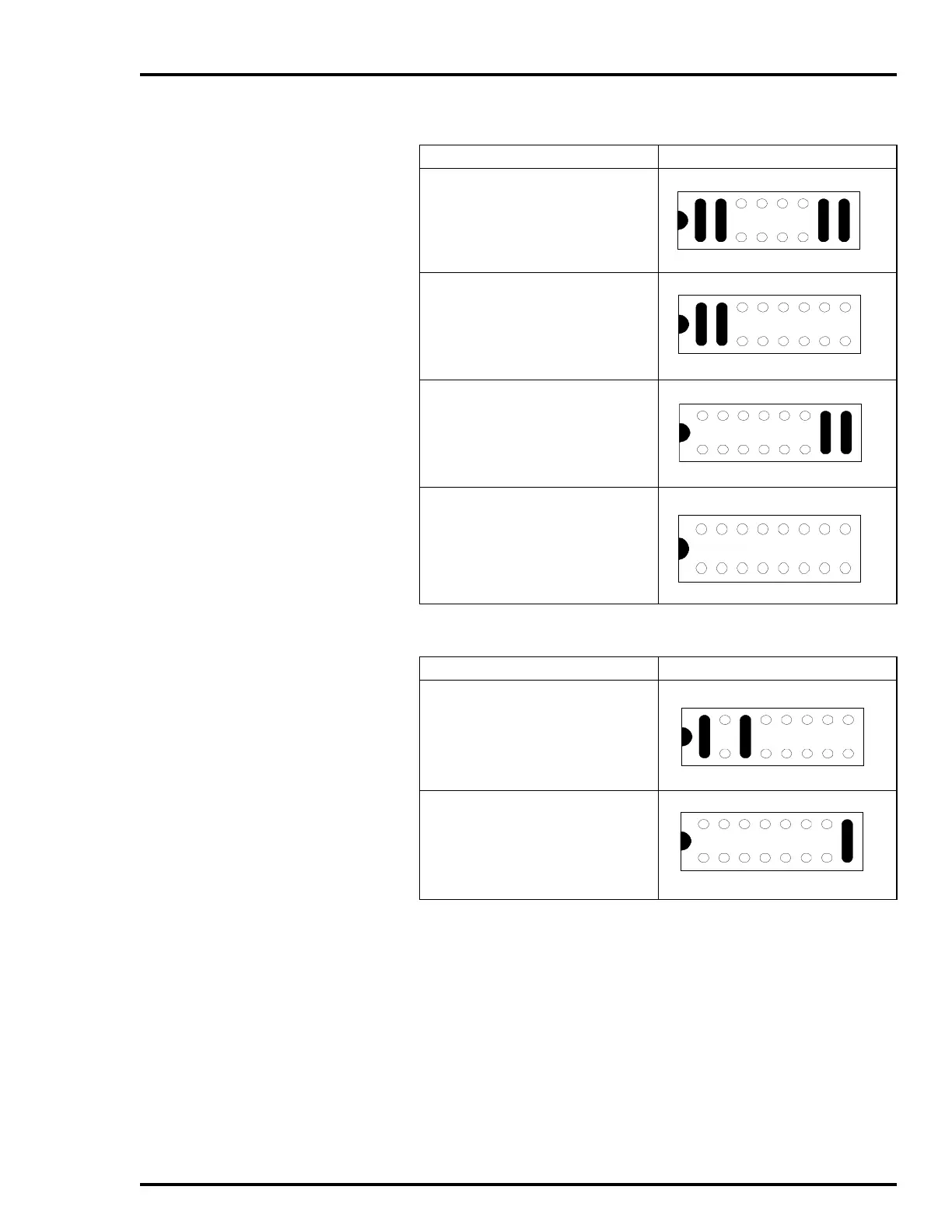
Table A-3. Analog Output Dipshunt Configuration
Application/Signal Type Dipshunt Configuration XU9
Both outputs in voltage mode
Output 1 in voltage mode, output 2 in
current mode
Output 1 in current mode, output 2 in
voltage mode
Both outputs in current mode (no dip-
shunt required)
Table A-4. Digital Input Dipshunt Configuration
Application/Signal Type Dipshunt Configuration XU5-XU7
System powered E3/E4
Field powered
1
NOTE:
1. Using the field device to complete the path to ground is commonly referred to as
switching neu-
tral
. Using the field device to complete the path to the I/O module is referred to as
switching hot
.
If switching hot is the desired method, the field powered dipshunt configuration must be used. If
system power is required, it should be wired as a field source. Refer to Figure A-2 for an example
of switching hot and switching neutral.