QUICK REFERENCE
INTRODUCTION
WBPEEUI240755B0 C - 3
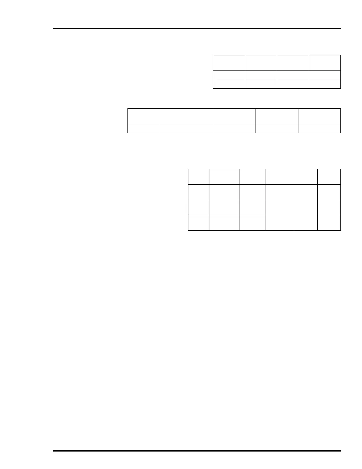
Table C-3. Analog Output Mode Jumpers
Analog
Output
Jumper
Current
Mode
Voltage
Mode
1 J9, J11 2-3 1-2
2 J13, J15 2-3 1-2
Table C-4. Analog Input Mode Jumpers
Analog
Input
Jumpers Current Mode
1
Voltage Mode
(Single Ended)
Voltage Mode
2
(Differential)
1, 2, 3, 4 J17, J18, J19, J20 1-2 3-4 —
NOTE:
1. Field/system powered analog inputs depend on TU/TM configuration.
2. Do not install jumpers for this configuration.
Table C-5. Digital Input Jumper Settings
Digital
Input
Jumper 120 VAC 125 VDC 48 VDC 24 VDC
1J1
J2
1-2
3-4
2-3
3-4
2-3
1-2
2-3
2-3
2J3
J4
1-2
3-4
2-3
3-4
2-3
1-2
2-3
2-3
3J5
J6
1-2
3-4
2-3
3-4
2-3
1-2
2-3
2-3