www.balluff.com 17english
8
Adjusting
NOTICE!
Interference in function
Adjustment while the system is running may result in
malfunctions.
► Stop the system before performing adjustment.
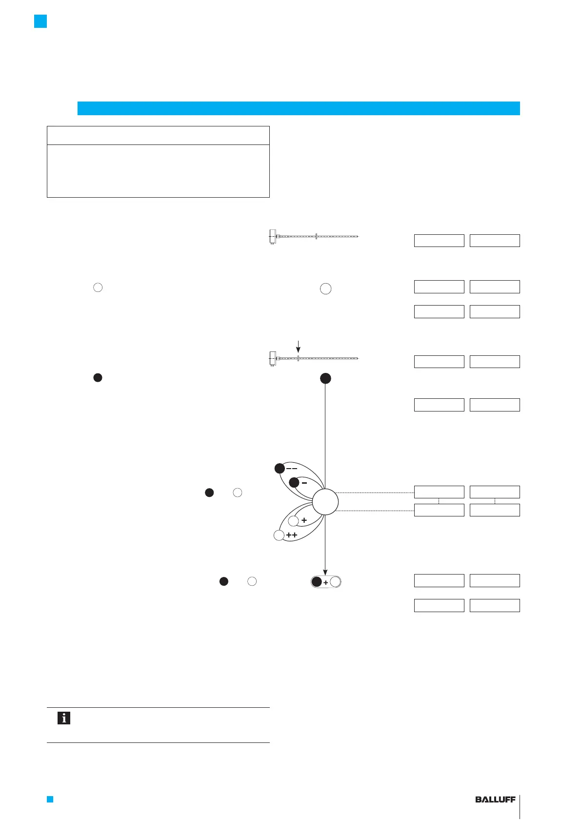
Displayed values (example)
At 0…10 V At 4…20 mA
Initial situation:
– Transducer with magnet within measuring range
5.39 V 9.15 mA
Activate adjusting
► Activate
for at least 4s.
>4s
2.00 V 6.00mA
⇒ Indication for adjustment is displayed.
⇒ The current position value is displayed again once
the button is released.
5.39 V 9.15 mA
Set start point
► Bring magnet to the new start point.
1.04 V 4.82 mA
► Activate
for at least 2s.
>2s
⇒ The new start point is set with the last valid start
value.
0.00 V 4.00 mA
Adjust start value
► The start value can be changed using
and
.
The gradient of the curve changes (see page 15).
0.00 V 4.00 mA
0.90 V 7.20 mA
► End calibration procedure: Briefly activate
and
simultaneously (<1s).
<1s
2.00 V 6.00mA
⇒ Set position value is saved.
0.90 V 7.20 mA
For setting the end point, adjusting the end value,
and ending adjustment, see page 18.
Any of the individual steps for settings can be
selected. The adjustment process can be
ended at any time.
a
b
b
BTL7-A/C/E/G5 __ -M ____ -K(8)-SR32/SR115/___
Micropulse Transducer - Rod Style

 Loading...


