18 english
a
b
b
8
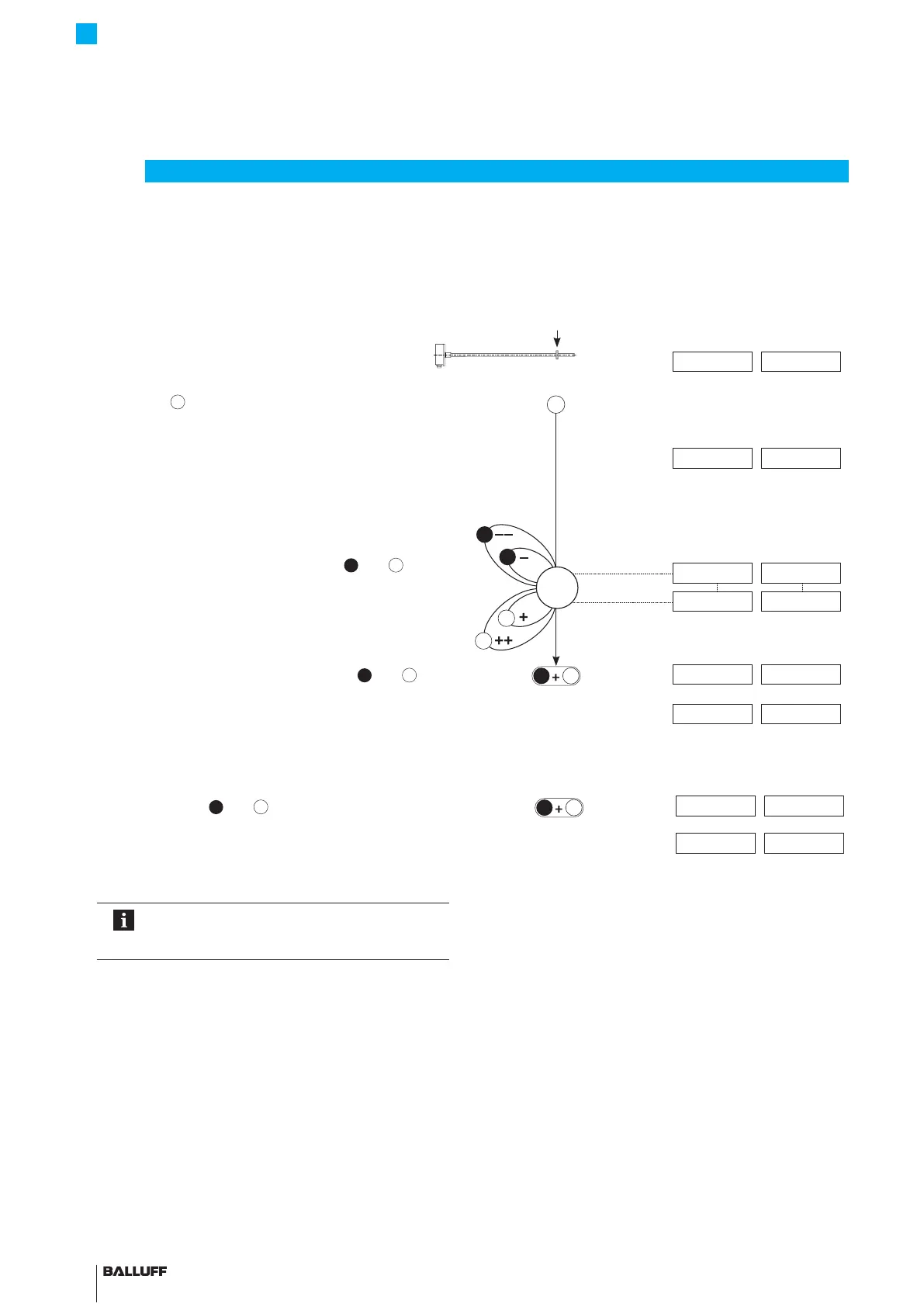
Adjusting (continued)
Displayed values (example)
At 0…10 V At 4…20 mA
Set end point
► Bring magnet to the new end point.
9.89 V 19.13 mA
► Activate
for at least 2s.
> 2s
⇒ The new end point is set with the last valid end
value.
10.00 V 20.00 mA
Adjust end value
► The end value can be changed using
and
. The
gradient of the curve changes (see page15).
10.00 V 20.00 mA
8.00 V 16.80 mA
► End calibration procedure: Briefly press
and
simultaneously (<1 s).
⇒ Set position value is saved.
< 1s
2.00 V 6.00mA
8.00 V 16.80 mA
End adjustment
► Briefly activate
and
simultaneously (<1 s).
< 1s
10.50 V 3.60 mA
⇒ The current position value is displayed once the
buttons are released.
7.63 V 18.56 mA
Any of the individual steps for settings can be
selected. The adjustment process can be
ended at any time.
BTL7-A/C/E/G5 __ -M ____ -K(8)-SR32/SR115/___
Micropulse Transducer - Rod Style

 Loading...


