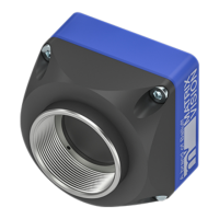
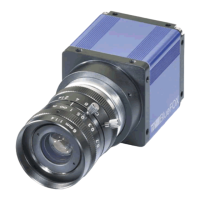
The mvBlueNAOS is a compact PCI Express board-level camera family from MATRIX VISION, compliant with the GenICam GenTL Producer standard. It integrates Sony IMX sensors with up to 16 LVDS lanes and a 4-lane PCI Express interface, supporting Generation 2 performance. This modular design makes it suitable for high-performance applications in fields such as medicine, reverse vending, traffic surveillance, 3D measurement, packaging, logistics, and robotics.
Function Description
The mvBlueNAOS camera family is designed for high data throughput, enabling large sensors to be fully exploited at high frame rates. It offers a wide range of sensors and resolutions, suitable for industrial applications, and features a modular design. The camera operates with a GenICam-compliant XML file that describes its capabilities, using names, units, and data types recommended by the Standard Feature Naming Convention (SFNC). Custom features developed by MATRIX VISION are prefixed with "mv".
The software concept for the mvBlueNAOS involves the mvIMPACT Acquire interface stacked on GenICam layers. mvIMPACT Acquire internally uses GenICam runtime libraries, functioning as a user application with the GenICam interface.
The device requires both hardware and corresponding software, installed via the mvIMPACT Acquire GenTL-Acquire package. This package includes:
- Firmware: Runs on the camera, controlling its hardware. It's stored on the camera and ensures operation during host boot-up. Firmware updates can be performed using the mvDeviceConfigure tool if there's a mismatch with the driver.
- Kernel Module: Facilitates communication between the hardware and the operating system. It's OS-specific and must match the GenICam producer layer.
- GenICam Producer: Provides the standardized GenTL interface, allowing communication with various SDKs (including MATRIX VISION SDK, HALCON, MIL, CVB, MATLAB, and other third-party packages).
- MATRIX VISION GenICam Consumer: Communicates with the camera via the GenTL interface and with the application through mvIMPACT Acquire functions.
The camera's acquisition control offers various modes:
- SingleFrame: Captures exactly one image.
- MultiFrame: Captures a set number of frames.
- Continuous: Captures images constantly until explicitly stopped by the application.
These modes support internal and external hardware triggers with selectable edges. The external trigger uses
ImageRequestTimeout (ms) to manage timeouts.
Advanced features include:
- MultiFrame / SingleFrame / Continuous acquisition modes.
- Auto Exposure Control (AEC) and Auto Gain Control (AGC).
- Auto White Balance (AWB).
- Binning / Decimation: Combines or reduces adjacent pixels to adjust sensitivity or resolution.
- Chunk Data Control: Allows inclusion of chunk data (e.g., timestamp, offset, width, height) in the image payload.
- Gamma: On-the-fly gamma correction on the camera.
- LUT: On-the-fly Look-Up Table processing on the camera.
- Digital I/O: 4 digital inputs and 4 digital outputs for industrial applications.
- Trigger Overlap: Specifies trigger overlap permitted with the previous frame, primarily for external triggers to minimize latency/jitter.
- Enhanced I/O functionality: Includes counter and timer controls.
- Event Control: Generates notifications for events like Exposure End, Line Rising/Falling Edge, and Frame End.
- User Sets: Stores up to five configuration sets (exposure, gain, AOI, frame rate, etc.) permanently on the camera.
- mvLogic Gate Control: Performs logical operations on multiple logic inputs to produce a single logic output.
- mvSerial Interface Control: Integrates motor lenses or other RS232-based peripherals.
- mvAuto Feature Control: Influences the characteristic of the AEC/AGC controller based on light situations, with properties like
mvAutoFeatureSensitivity, mvAutoFeatureCharacteristic, and mvAutoFeatureBrightnessTolerance.
Important Technical Specifications
The mvBlueNAOS is available in two main series: mvBlueNAOS2 and mvBlueNAOS4, with various sensor configurations.
General Specifications (mvBlueNAOS2 / mvBlueNAOS4):
- Image Memory: 16 MByte (Flash for FPGA Configuration, Device Specific Data).
- PCIe Interface: x4 Gen2.
- PCIe Bandwidth max.: 16 Gbit/s.
- Max. effective PCIe Bandwidth: 12.8 Gbit/s.
- Bandwidth FPGA Pipeline: 800 MPixel/s (mvBlueNAOS2) / 1300 MPixel/s (mvBlueNAOS4).
- SLVS Lanes: 16 (mvBlueNAOS2) / 4 (mvBlueNAOS4).
- Inputs/Outputs: 4 digital inputs, 4 digital outputs.
- RS232: For controlling varioptic liquid lenses, lights, etc.
- Ambient Temperature (Operation): 0 to 45 °C / 30 to 80% RH.
- Storage Temperature: -20 to 60 °C / 20 to 90% RH.
- Protection class: IP30.
- Weight without lens: approx. 71 g (mvBlueNAOS2) / approx. 81.6 g (mvBlueNAOS4).
- Power supply (PWR_IN): 4 W (mvBlueNAOS2) / 6 W (mvBlueNAOS4).
NAOS for Embedded (N4e) Interface:
- Connector: Hirose DF40GB(3.0)-70DS-0.4V (camera) and DF40GB-70DP-0.4V (mating).
- Mechanical Characteristics: 70-pin, 0.4mm pitch, shielded, stacking height: 3.0mm. Screws M1.6, max. screw depth 1.8mm.
- Input Voltage (VCC_IN): 5-12V (min 5V, nom 12V, max 17V).
- Current (IVCC_IN): 1.8A.
- VCC_IO: 1.8V, 3.3V, 5.5V.
- Digital I/Os: Include Level Shifters for customized I/O levels.
- Serial Interface (RS232): Max Data Rate 115 kbps.
- I2C_USER: Interface clock rate 100-400 kHz.
OCuLink Interface:
- Connector: Amphenol type G14A42211912HRV (camera).
- Power-In (PWR_IN): 5V (min), 2A (IVCC_IN).
- Power/IO Connector (for OCuLink model): 10-Pin Samtec Connector (TFM-105-02-L-D-WT, 1.27 mm pitch).
- Opto-isolated Digital I/O: Opto DigIn 0 & 1 and Opto DigOut 0 & 1 are galvanically isolated (0.5mm Pitch → 1kV isolation).
- TTL Level Digital I/O: DigIn2, DigOut2.
Sensor Data (Examples):
- IMX273 (1.6 Mpix, 1456x1088): Max. FPS 226.5, SNRmax 40.1 dB, DNR 71.1 dB, Unit cell size 3.45µm.
- IMX540 (24.6 Mpix, 5328x4608): Max. FPS 55.5, SNRmax 39.8 dB, DNR 70.2 dB, Unit cell size 2.74µm.
Usage Features
The mvBlueNAOS is designed for ease of use with graphical user interface (GUI) tools:
- wxPropView: Allows image acquisition, device configuration, and display/modification of device properties. It includes a Quick Setup Wizard for first-time use and a Multi AOI wizard for defining multiple Areas of Interest.
- mvDeviceConfigure: Used to set the device ID, update firmware, and disable CPU sleep states (Windows only). It also facilitates registering devices for DirectShow access and renaming them.
Acquisition and Image Quality:
- Acquiring multiple images: Configurable via
AcquisitionMode (MultiFrame) and Acquisition Frame Count. Can be triggered externally.
- Long exposure times: Achieved by using timers to generate external exposure signals, especially for sensors supporting
ExposureMode TriggerWidth.
- Multiple AOIs (mv Multi Area Mode): Define up to eight Areas of Interest in one image to increase frame rate. The output image combines these AOIs, filling missing areas with image data.
- Event Control: Set up event notifications (Exposure End, Line Rising/Falling Edge, Frame End) and attach custom callbacks for specific property modifications.
- Correcting image errors: Detect and correct leaky, hot, or cold pixels using
mvIMPACT Acquire's calibration methods. Correction data can be stored on the device. Adaptive/algorithm-based correction works on-the-fly for binning/decimation modes.
- Optimizing color/luminance fidelity: Perform gamma correction (using AnalogControl or LUTControl), white balance, contrast adjustment, and saturation/color correction (using Color Transformation Control wizard).
- Flicker-free auto exposure and auto gain: Adapt camera frequency to AC light frequency using timer-based external triggers to avoid oscillations.
- Binning / Decimation: Combine or reduce adjacent pixels to increase sensitivity (Sum mode) or signal/noise ratio (Average mode).
Triggering:
- Incremental encoder processing: Use counters (
Counter and CounterEnd) to synchronize images with encoder pulses.
- Pulse Width Modulation (PWM): Generate PWM signals using two timers for applications like dimming laser line generators.
- Outputting pulses: Configure timers to output pulses at specific intervals or after a certain number of external triggers.
- Detecting overtriggering: Use counters to compare incoming trigger signals with
ExposureStart signals, and overlay chunk data in the live image to visualize skipped triggers.
- Low latency triggering: For Pregius global shutter sensors,
mvLowLatency mode starts exposure directly on the trigger, eliminating latency and jitter.
- Indefinite sequence with precise starting time: Use a timer and logical AND/OR gates to achieve precise, low-latency triggered acquisition for indefinite sequences.
Working with I/Os:
- Controlling strobe or flash: Use
mvExposureAndAcquisitionActive to control output lines for strobe/flash, synchronizing with exposure time. mvExposureActiveShiftEnable allows shifting the signal.
- Debouncing filter: Eliminate noise on trigger lines by configuring
mvLineDebounceTimeRisingEdge and mvLineDebounceTimeFallingEdge properties for digital inputs.
Saving Data on the Device:
- User data entries: Save arbitrary user-specific data (String or Binary) to the camera's non-volatile memory.
- User set entries: Store up to five configuration sets (exposure, gain, AOI, frame rate) permanently on the camera, independent of the computer.
- UserFile section (Flash memory): Upload or download custom files to a 64 KByte section of Flash memory using
File Access Control.
Device Features:
- Temperature sensors: Monitor temperature on the sensor board and FPGA board. Output can be configured to drive a fan or heating system based on temperature limits and hysteresis.
- Reset timestamp by hardware: Synchronize timestamps across multiple cameras using a defined signal edge from a master camera or external process.
- Synchronizing camera timestamps: Use
mvTimestampReset, Pulse-per-second (PPS) signals, or mvDeviceTimeSync (mvSystemTime, mvNoSynchronization, mvPushSynchronization) to synchronize camera timestamps with each other or with the host PC.
- Serial Interface: Control motor lenses or other RS232-based peripherals.
Maintenance Features
- Handling and Cleaning:
- Do not attempt to disassemble the camera.
- Avoid water or dust entering the camera when installing/removing lenses.
- Clean the case with a dry soft cloth and neutral detergent if needed. Do not use benzene, thinner, alcohol, or spray-type cleaners.
- Use a blower or lens brush to remove dust from the lens or optical filter. Do not disassemble the front flange.
- Installation:
- Avoid direct sunlight, rain, snow, combustible/corrosive gas, excessive heat (0 to 45 °C ambient), humidity, dust, excessive vibration/shock, or strong electric/magnetic fields.
- Mount the camera on a thermoconducting surface (e.g., aluminum).
- Do not aim the camera at the sun or strong light sources to prevent sensor damage.
- Ensure sufficient cooling, as single components can reach high temperatures. Inadequate cooling invalidates the guarantee. A thermal conduction plate is recommended.
- Camera case temperature should not exceed 65 °C. Mainboard temperature should not exceed 80 °C.
- Connectors:
- Confirm power is off before connecting or disconnecting signal cables.
- Grasp connectors by the body, not the wires.
- Be careful when bending the flex cable (minimum bending radius approx. 3 mm).
- Electrostatic Discharge (ESD):
- Take proper ESD precautions during hardware installation.
- Discharge body static by touching a grounded surface.
- Avoid plastic, vinyl, and Styrofoam (except anti-static versions) around printed circuit boards.
- Do not touch components on the printed circuit board with bare hands or conductive devices.
- Troubleshooting:
- Access log files (Windows: wxPropView, Linux:
/opt/mvIMPACT_Acquire/data/logs) for support.
- Address common issues like increasing error counters by disabling CPU sleep states (C-States, EIST, ASPM) in BIOS settings and PCI Express Link State Power Management in Windows.
- Resolve "Bluescreen On Machines Running Windows 10 Or Higher When Streaming Is Started" by updating mvIMPACT Acquire, disabling IOMMU (VT-d, Intel VT for Directed I/O, AMD Vi), or disabling "DMA Protection" in BIOS.
- Resolve "No GenICam devices are detected on a Linux system" by using a login-shell or inserting environment variables from
/etc/profile.d/genicam.sh and /etc/profile.d/acquire.sh into a shell configuration file.
- Optimize device list updates by deselecting unused interfaces or devices in wxPropView.