1.9 Technical Data 47
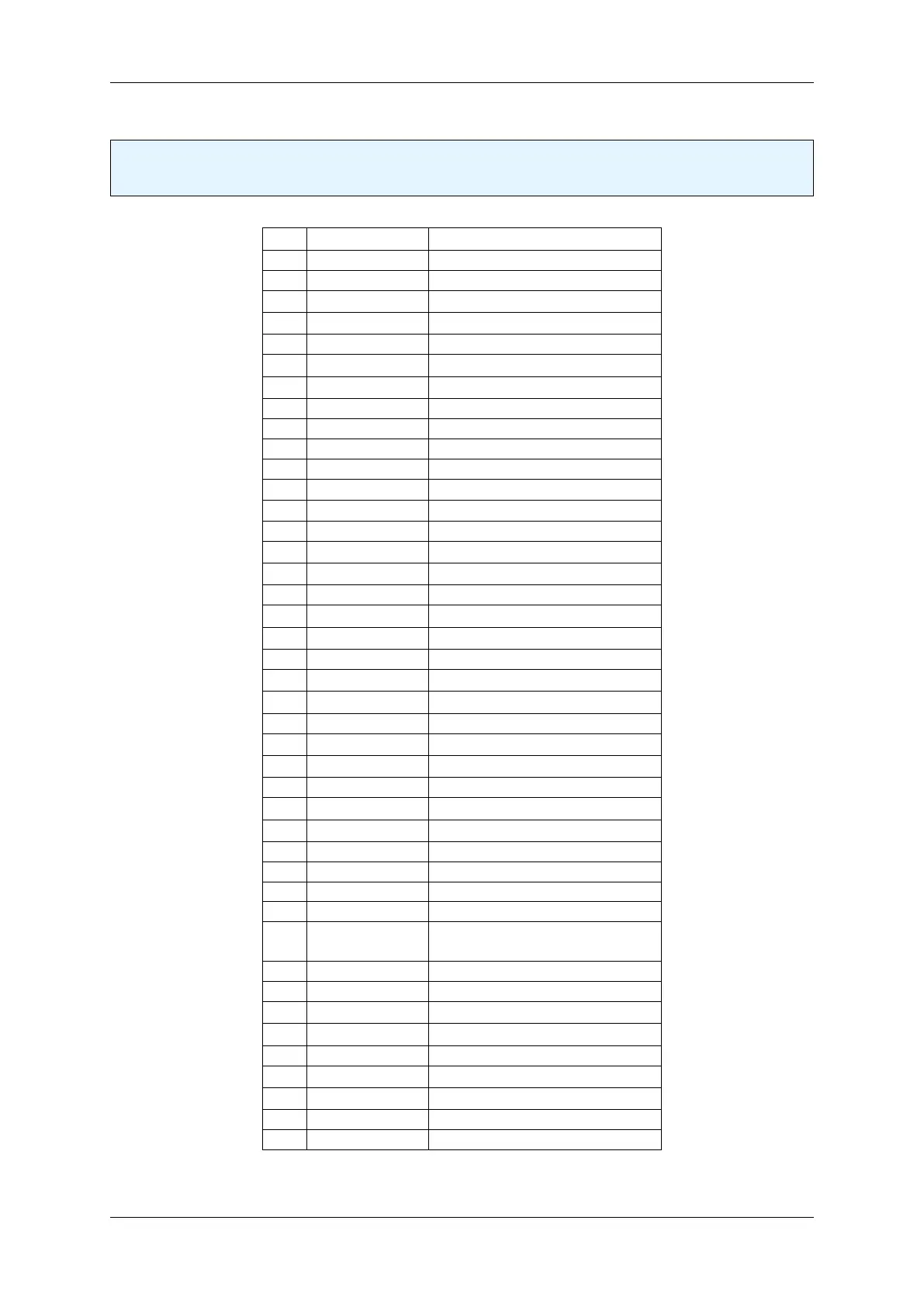
1.9.4.1 Pin assignment
Note
The red dot marks pin 1.
Pin Signal Description
A1 - Do not connect
A2 GND Ground
A3 PCIe_RX0_P PCIe Receiver IN (differential)
A4 PCIe_RX0_N PCIe Receiver IN (differential)
A5 GND Ground
A6 PCIe_RX1_P PCIe Receiver IN (differential)
A7 PCIe_RX1_N PCIe Receiver IN (differential)
A8 GND Ground
A9 - Do not connect
A10 WAKE_PCIE IN CWAKE
A11 GND Ground
A12 PCIe_CLK_P IN PCIE_CLK +
A13 PCIe_CLK_N IN PCIE_CLK +
A14 GND Ground
A15 PCIe_RX2_P PCIe Receiver IN (differential)
A16 PCIe_RX2_N PCIe Receiver IN (differential)
A17 GND Ground
A18 PCIe_RX3_P PCIe Receiver IN (differential)
A19 PCIe_RX3_N PCIe Receiver IN (differential)
A20 GND Ground
A21 PWR_IN (p. 52) Power-In
B1 PWR_IN (p. 52) Power-In
B2 GND Ground
B3 PCIe_TX0_P PCIe Transmitter OUT (differential)
B4 PCIe_TX0_N PCIe Transmitter OUT (differential)
B5 GND Ground
B6 PCIe_TX1_P PCIe Transmitter OUT (differential)
B7 PCIe_TX1_N PCIe Transmitter OUT (differential)
B8 GND Ground
B9 - Do not connect
B10 - Do not connect
B11 GND Ground
B12 PCIe_PERST←-
_N
IN Reset
B13 CPRSNT IN PRESENT
B14 GND Ground
B15 PCIe_TX2_P PCIe Transmitter OUT (differential)
B16 PCIe_TX2_N PCIe Transmitter OUT (differential)
B17 GND Ground
B18 PCIe_TX3_P PCIe Transmitter OUT (differential)
B19 PCIe_TX3_N PCIe Transmitter OUT (differential)
B20 GND Ground
B21 - Do not connect
Directions of the PCIe signals (Transmitter/Receiver) are from the FPGA to the add-in card.
MATRIX VISION GmbH