WWW.BALLUFF.COM • 1-800-543-8390
7
Micropulse Linear Position Transducer
Absolute Quadrature Output
Rod Style & Profile Style Housings
A
A
B
B
Z
Z
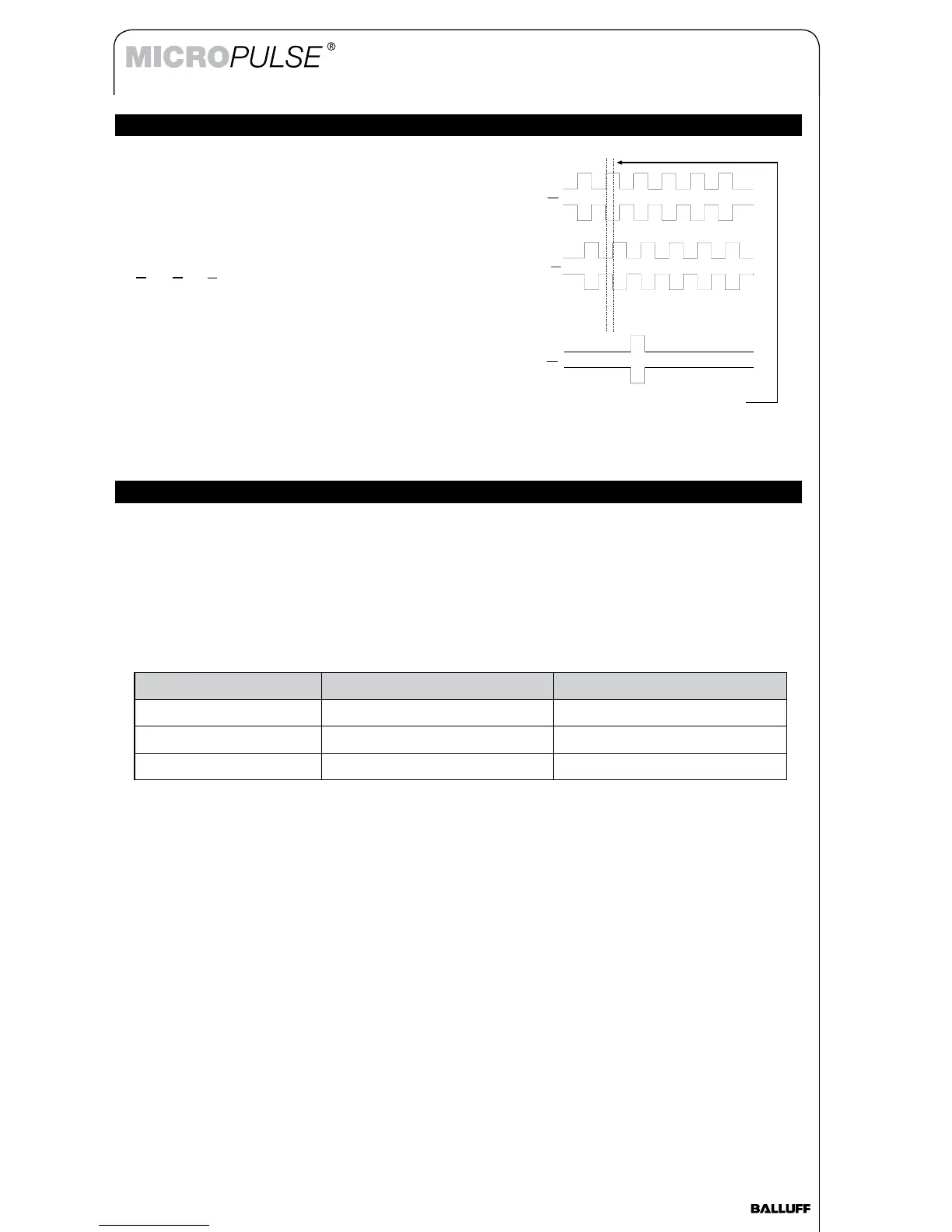
The Micropulse quadrature-output linear transducers
produce an AB quadrature output signal. The A and B
channels are 90° out of phase depending on the direction of
position travel. In addition a programmable Z pulse can be
set anywhere within the active stroke to represent a “home”
or “zero” position. The RS422/RS485 differential line driver
provides each output, along with its complementary signal
(A, A, B, B, Z, Z).
Absolute position information from the transducer is used
to generate incremental position updates. Any change in
linear position causes the appropriate number of pulses to
be delivered to the output. In addition, the absolute position
value can be delivered to the output at any time by using
the STROBE input to create a “burst” of pulses that is equal
to the absolute (relative to the “zero” point) position (see
STROBE instructions below).
Operating Instructions
90° phase shift between A and B
In this example, B lags A by 90°,
indicating FORWARD position change
Operating Modes
The Micropulse quadrature-output linear transducer is capable of operating in the following modes, which
are selected via the ordering code (see pg. 10):
Free-Run Mode – In this mode, the transducer output updates at a periodic rate determined by the
Update Rate parameter in the ordering code. As long as power is applied to the transducer, the
transducer provides a position output. This is the most common mode of operation.
Note – Maximum allowable free-running update rate is limited by transducer stroke length.
Use the following table to determine maximum permissible update rate:
Synchronous Mode – (ordering code Qxxx0) In this mode, the transducer synchronizes itself to an
external controller via the STROBE input. This mode can only be used in conjunction with motion control-
lers that support this function, e.g., Allen-Bradley IMC-S class controllers. For more information, please
consult factory.
Stroke Length (mm) Allowable Update Rates Ordering Code (see page 10)
< 1250 mm 1 ms, 2 ms or 4 ms Qxxx1, Qxxx2, or Qxxx4
1251 to 2500 mm 2 ms or 4 ms Qxxx2 or Qxxx4
> 2500 mm 4 ms Qxxx4