EasyManuals Logo

Balluff MICROPULSE Series User Manual

Balluff MICROPULSE Series
12 pages
To Next Page IconTo Next Page
To Previous Page IconTo Previous Page
Page #4 background imageLoading...
Page #4 background image
1-800-543-8390 WWW.BALLUFF.COM
4
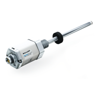
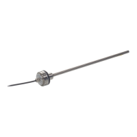
Micropulse Linear Position Transducer
Absolute Quadrature Output
Rod Style & Profile Style Housings
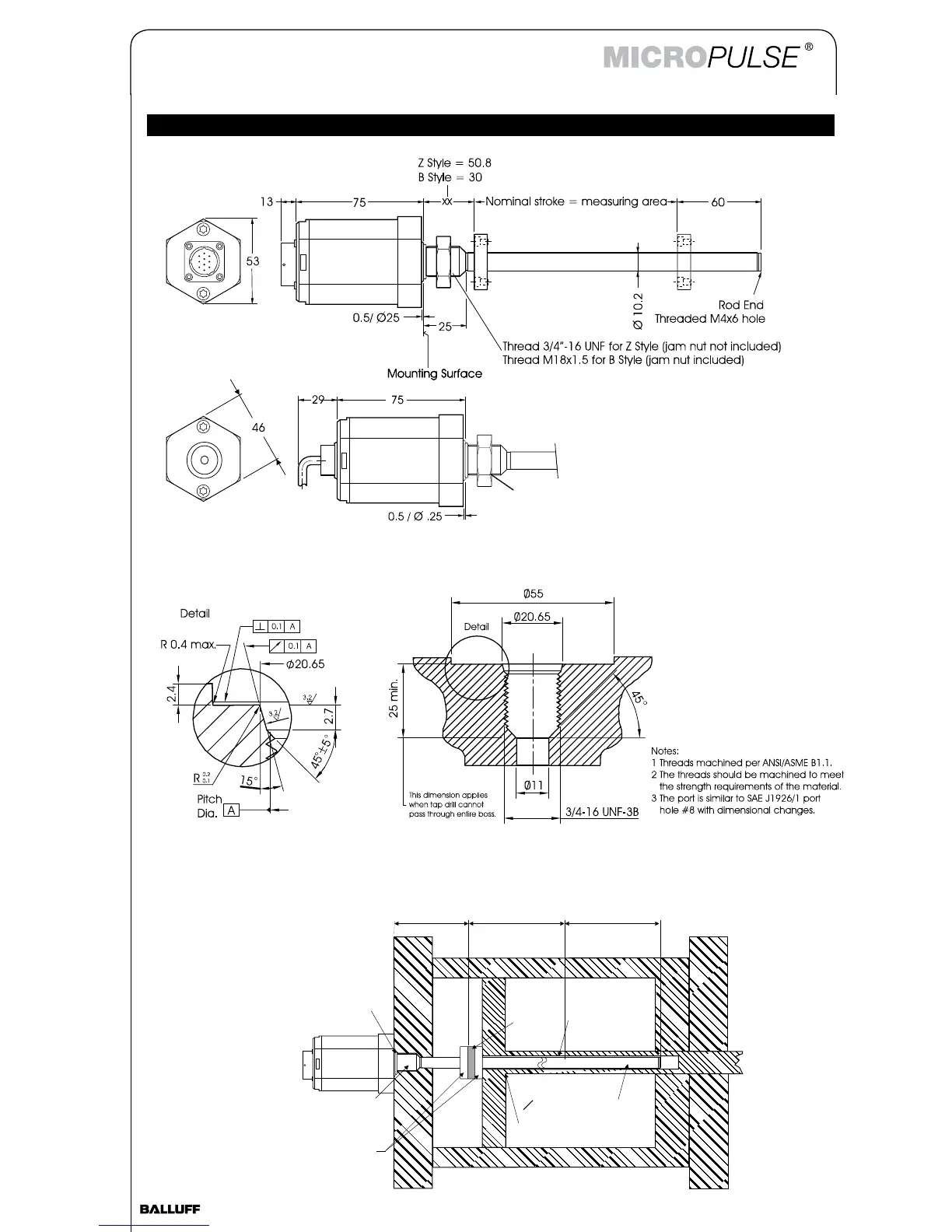
Mechanical Dimensions/Installation – Rod Style Housing
Cylinder Port Dimensions
Jam Nut
BTL5-JAM-NUT
For 3/4" - 16 UNF (Z style)
Order separately if required
Stroke Length
60 mm
Dead Zone
Sensor Rod
O 10.2mm(0.401in)
Piston Head &Rod Assembly
Magnet
12.7mm (0.5 in)Bore
3/4-16UNF-3AThreads
or M18x1.5 Metric Threads.
O-ring
Non-ferrous Spacers
NullZone
50.8mm(2in.)Standard
30 mm (Optional)
Typical Cylinder Installation
Mechanical Dimensions

Questions and Answers:

Question and Answer IconNeed help?

Do you have a question about the Balluff MICROPULSE Series and is the answer not in the manual?

Balluff MICROPULSE Series Specifications

General IconGeneral
Measurement PrincipleMagnetostrictive
OutputAnalog, Digital (SSI, Profibus)
Operating Voltage10 VDC to 30 VDC
Protection ClassIP67
Temperature Range-40°C to +85°C
Housing MaterialStainless steel or aluminum
Linearity±0.02% F.S. (depending on model)
Electrical ConnectionM12 connector
ResolutionUp to 1 μm (depending on model)

Related product manuals