• The device mounting and connections, must be carried out by qualified personnel only, according to the instructions
included in the mechanical installation and electrical connection sections of this manual and applicable standards.
•
The safety laser scanner must be securely placed in a particular position so that access to the dangerous zone is
not possible without passing through the Safety Zone of the scanner.
• The personnel operating in the dangerous area must be well training and must have adequate knowledge of all the
operating procedures of the machine and safety laser scanner.
• In cases of Manual Restart, the reset button must be located outside the safety area, see the reset switch location
section of this manual.
• The requirements for electrical safety and electromagnetic compatibility and the regulations or standards in all
countries and/or regions, must be met by the power supply where the laser scanner is used. If the device power
supply is shared with the machine or other electronic devices, voltage fluctuations to the laser scanner or noise
influences to the scanner may occur due to temporary changes of the current consumption on the machine or the
other electronic devices. We do not recommend sharing the laser scanner power supply with the one for the
machine or the other electronic devices, because the device may go to an error state in such circumstances.
•
Do not run the connection cables in contact with or near high-voltage cables and/or cables which undergo large
current variations (i.e. motor power supplies, inverters, etc.).
• Access to the configuration tools must be restricted to only highly qualified personnel. The configuration upload
process through the GUI is allowed only by password.
2.11
Specifications
2.11.1 Specifications
Power Consumption
No output load: 8 W at 24 V dc
With maximum output load: 27 W at 24 V dc
Power-up delay: 40 seconds, typical
Current Consumption (24 V dc)
No output load: 0.3 A at 24 V dc
With maximum output load: 1.1 A at 24 V dc
Static Input Generic
Input voltage high: > 12 V
Input voltage low: < 5 V
Input current high: 2 mA at 24 V dc
Input impedance: 12 kΩ
Connectors
I/O and power: M12 male type A connector (8 poles)
Ethernet to GUI or Data transmission: M12 male type D connector (4
poles)
Power and Electrical Protection
Protection class: III ( EN 61140 / IEC 61140 )
Supply voltage: Uv 24 Vdc (19.2 V … 30 Vdc) (SELV/PELV)
2
Residual ripple: ± 5%
3
Start-up current (1): < 0.6 A
4
The Scanner should be connected only to a SELV (Safety Extra-Low
Voltage) for circuits without earth ground or a PELV (Protected Extra-
Low Voltage) for circuits with earth ground power supply.
Light Beam Diameter
At front screen: 8 mm
At middle field distance: 10 mm
At max distance: 20 mm
Detectable remission: 1.8% to 1000%
Maximum homogeneous contamination of the optics cover without
preventing the detection capability –30% of nominal optic power
Output (warning and generic)
Output logic and protection: PUSH-PULL, Overcurrent protection
Output voltage for ON status (HIGH): Uv–2 V at 250 mA
Output voltage for OFF status (LOW): 0 V
Output current for ON status (HIGH): 250 mA
Leakage current: < 700 μA
5
Load inductance: 2 H
Load capacity: 2.2 µF
Optical Data
Wavelength: 905 nm
Pulse duration: 3 nsec
Average output power: 8 mW
Laser class: CLASS 1 (EN 60825-1)
Divergence of collimated beam: 0.12°
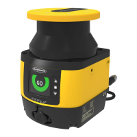
Mechanical Data
Dimensions (W × H × D): 102 × 152 × 112.5
Weight (including system plug): 1.5 kg
Housing material: Aluminum Alloy
Housing color: Yellow RAL1003
Optics cover material: PC
Optics cover surface: Acrylic
OSSD (Safety Output)
OSSD logic and protection: PUSH-PULL, Overcurrent protection
Output voltage for ON status (HIGH): Uv–2V at 250 mA
Output voltage for OFF status (LOW): 0 V
Output current for ON status (HIGH): 250 mA
Leakage current: < 700 μA
6
Max Load inductance: 2 H
Max Load capacity: 2.2 µF
Test pulse width: 300 µs
Test pulse interval: 167 ms
OFF status duration: 900 ms
Latency time between output pair: 450 ms
2
To meet the requirements of the relevant product standards (e.g. EN 61496-1), the external voltage supply for the devices (SELV) must be able to bridge a brief mains failure of 20 ms.
Power supplies according to EN 60204-1 satisfy this requirement.
3
The absolute voltage level must not drop below the specified minimum voltage.
4
The load currents for the input capacitors are not taken into account.
5
In the case of a fault (0 V cable open circuit) maximally the leakage current flows
in the OSSD cable. The downstream controller must detect this status as LOW. A FPLC (fail-safe
programmable logic controller) must be able to identify this status.
6
In the case of a fault (0 V cable open circuit) maximally the leakage current flows in the OSSD cable. The downstream controller must detect this status as LOW. A FPLC (fail-safe
programmable logic controller) must be able to identify this status.
SX5 Safety Laser Scanner
20 www.bannerengineering.com - Tel: +1.763.544.3164
 Loading...