WARNING: EDM Monitoring. If the System is configured for “No Monitoring,” it is the user’s responsibility
to ensure that this does not create a hazardous situation. Failure to follow these instructions could result
in serious injury or death.
4.3.4 Warning (Auxiliary) Output
The scanner can have pins 1, 3, or 4 set as a Warning Output(s). One warning output can be selected when one or two zone
sets are configured.
Two warning outputs can be selected when one zone set with one safety zone and two warning zones
is configured. These outputs provide a PNP current-souring output (250 mA maximum) that switches ON when the defined
and active warning field is cleared and switches OFF when the active warning field is interrupted.
4.3.5 Preparing for System Operation
After the initial trip test has been performed (see
Perform a Trip Test
on page 50), and the OSSD safety output
connections have been made to the machine to be controlled, the SX5 is ready for testing in combination with the guarded
machine.
The operation of the SX5 with the guarded machine must be verified before the combined SX5 and machine may be put
into service. To do this, a Qualified Person must perform the Commissioning Checkout Procedure described in
Checkout
Procedures
on page 78.
4.3.6 Machine Interface Connections
The SX5 Safety Laser Scanner model has one OSSD pair and includes three
configuration signals.
These signals allow the user to configure the scanner with different functions:
•
Signaling when a person or an object is in a Warning Zone
• Switching the detection areas using external signals (Area Switch)
• Restarting the device using a Manual reset (restart) and restoring the device after a fault condition (reset)
• Muting the whole safety area and the single line pattern mute dependent override
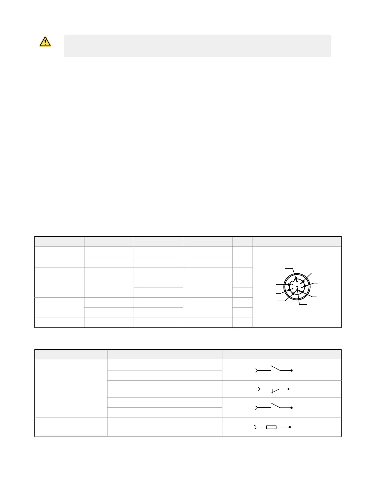
Type Signal Color Description Pin
Power
Power supply Brown 24 V dc 2
GND_ISO Blue 0 V 7
Input/Output Multi in/out
Green
Software selectable
3
Yellow 4
White 1
Safety output
OSSD 1/1 Gray
Safety output
5
OSSD 1/2` Pink 6
Other F_EARTH Red Functional Earth 8
The Multi in/out pins can be configured either as an input or an output.
Signal Function Connection
Multi In
Restart/Reset
Area switch
Override (single line pattern)
Muting 1 Muting 2
Muting Enable
Multi Out Warning
SX5 Safety Laser Scanner
www.bannerengineering.com - Tel: +1.763.544.3164 45