Ambient Interferences present Z
amb
= Value interpreted from the graph based on dust
filter level
Figure 26. Calculating the safety distance for each resolution
US Information Dpf Considerations for Vertical Safety Zone Applications (Normal Approach)
For Detection Capability (Resolution), where d ≤ 64 mm (2.5 in), i.e. 40 mm, the formula for Dpf is: Dpf = 3.4 x (d - 7 mm) or
Dpf = 3.4 x (d - 0.275 in)
Where d = the scanner's detection capability (resolution)
For Detection Capabilities (Resolution) of d > 64 mm (2.5 in), i.e. 70 mm, Dpf is 900 mm (36 in)
For a Detection Capability (Resolution) of 40 mm the Dpf is 112 mm (4.5 in)
European Information Distance Adjustment C, Based on the Possible Field Intrusion for Vertical Safety Zone
Applications (Normal Approach)
For a Resolution of 40 mm (1.6 in), the formula for C is: C = 8 x (d - 14 mm) or C = 8 x (d - 0.55 in)
Where d = the scanner's detection capability (resolution)
For a resolution of 70 mm (2.8 in): C = 850 mm (34 in)
For a Detection Capability (Resolution) of 40 mm, C is 208 mm (8.2 in)
3.6 Reducing or Eliminating Pass-Through Hazards
A
pass-through
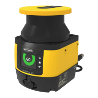
hazard is associated with applications where personnel may pass through a safeguard, such as the SX5
Safety Laser Scanner (which issues a stop command to remove the hazard), and then continues into the guarded area. This
is common in access and perimeter guarding applications. Subsequently, their presence is no longer detected, and the
related danger becomes the unexpected start or restart of the machine while personnel are within the guarded area.
A pass-through hazard typically results from large safety distances calculated from long stopping times, large minimum
object sensitivities, reach-over, reach-through, or other installation considerations. A pass-through hazard can be generated
with as little as 75 mm (3 in) between the sensing field and the machine frame or hard (fixed) guarding.
Eliminate or reduce pass-through hazards whenever possible. While it is recommended to eliminate the pass-through
hazard altogether, this may not be possible due to machine layout, machine capabilities, or other application
considerations.
One solution is to ensure that personnel are continually sensed while within the hazardous area. This can be accomplished
by using supplemental safeguarding, such as described by the safety requirements in ANSI B11.19 or other appropriate
standards.
An alternative method is to ensure that once the safeguarding device is tripped it will latch and will require a deliberate
manual action to reset. This method of safeguarding relies upon the location of the reset switch as well as safe work
practices and procedures to prevent an unexpected start or restart of the guarded machine. The SX5 Safety Laser Scanner
provides a configurable Manual Start/Restart (Latch Output) function for these applications.
SX5 Safety Laser Scanner
www.bannerengineering.com - Tel: +1.763.544.3164 31
 Loading...