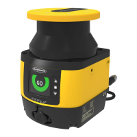
3. Use the test piece to interrupt the perimeter of the Safety Zone.
The display when a test piece interrupts the Safety Zone
4. Remove the test piece and verify the display returns to the green Go display shown in step 1.
5.
Repeat this test along the entire Safety Zone perimeter and verify that the
configured zone:
• Responds to the intrusion of the test piece.
• Has no unmonitored areas as described in
Unmonitored Areas
on page 23.
• Complies with the Safety Distance calculated in
Minimum Safety (Separation) Distance Formula
on page 30.
Pay special attention at needle- and cone-shaped areas.
6. For stationary applications, verify that the marking of the perimeter of the Safey Zone on the floor corresponds with
the status of the display. If the floor
has not been marked, do so now, with the aid of the display response.
7. Verify the height of the Safety Zone at the perimeter is at the expected level (for example, 150 mm for mobile
applications):
• Safety Zones of 180 ° to 275°—Verify the height in at least four locations, approximately 90° apart from each
other.
• Safety Zones of 90° to 180°—Verify the height in at least three locations, approximately 90° apart from each
other.
• Safety Zones of 90° or less—Verify the height in at least two locations, approximately 90° apart from each other
Figure 40. Safety Zone angles and locations for verification
Figure 41. Safety Zone height
8. If Zone Set switchover is used, repeat steps 1 through 7 for each Zone Set that has been configured. Ensure all
fields correspond to the expected fields as determined by the risk assessment. If not, do not continue until the
situation is corrected.
9. After all corrections and changes to the configuration and the Safety and Warning Zones have been verified,
proceed to Electrical Interface to the Guarded Machine.
WARNING: If the Trip Test Indicates a Problem
If the SX5 System does not respond properly to the trip test, do not attempt to use the System. If this
occurs, the System cannot be relied on to stop dangerous machine motion when a person or object
enters the sensing
field. Failure to follow these instructions could result in serious injury or death.
Other checks to carry out include:
•
Performing system checkouts to ensure the continued reliable operation. Banner Engineering highly recommends
performing the system checkouts as described in the checkout procedures. However, a Qualified Person should
evaluate these recommendations, based on the specific application and the results of a machine risk assessment, to
determine the appropriate content and frequency of checkouts.
•
Designing the Safety Zone so that the approach towards any dangerous point of the machine can only be accessed
by passing through the Safety Zone, and the distance that a person has to cover must be longer than the minimum
safety distance.
SX5 Safety Laser Scanner
www.bannerengineering.com - Tel: +1.763.544.3164 51

 Loading...