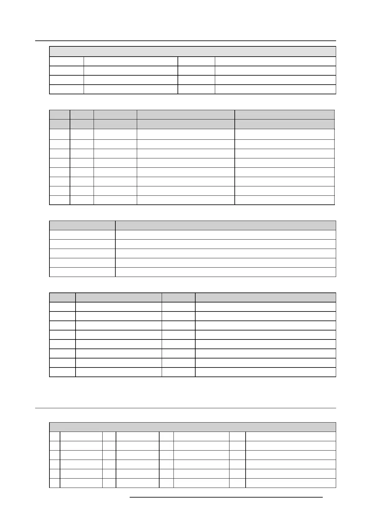
A. Pin configurations
General Purpose In/Out
16
GPOUT 8 P
35
GPOUT 8 N
17 reserved 36 re se rved
18 reserved 37 re se rved
19 reserved
Ethernet port
10/100 Base-T — RJ45 port 1000 Base-T — RJ45 p ort
Pin Pair Color Description Description
13
white/green
TXD+ TX0+
23
green
TXD- TX0-
32
white/orange
RXD+ RX0+
4 1 blue
—
TX1+
51
white/blue
—
TX1-
62
orange
RXD- RX0-
74
white/brown
—
Rx1+
8 4 brown
—
RX1-
Peripheral Port
Pin Name
1+5V
2
SCL
3
SDA
4 +24V
5
GND
3D connector
Pin Name Pin Name
1 +12V 9 +12V
2 Grnd 10 3D Input Reference -
3 Grnd 11 3D Display Reference +
4 RS232 RX 12 3D Display Reference -
5
RS232 TX 13 CONN_3D MODE -
6 CONN_3D_MO DE + 14 CONN_SYNC -
7
CONN_SYNC + 15
-
8 3D Input Reference +
A.3 Pin configurations of the inputs
DVI-D
DVIINA&B
1RX2-
7
DDC Data
13
nc
19
RX0 Shield
2RX2+ 8
nc
14 +5V 20
nc
3
RX2 Shield
9RX1- 15
GND
21
nc
4
nc
10 RX1+ 16 Hot Plug D etect 22
TMDS Clock S hield
5
nc
11
RX1 Shield
17 RX0- 23
TMDS RXC+
6
DDC Clock
12
nc
18 RX0+ 24
TMDS RXC -
R5905050 DP2K C-SERIES 10/07/2012 101
 Loading...


