12. Convergence
Convergence test pattern
4
1
2
5
3
6
3
6
2
5
4
1
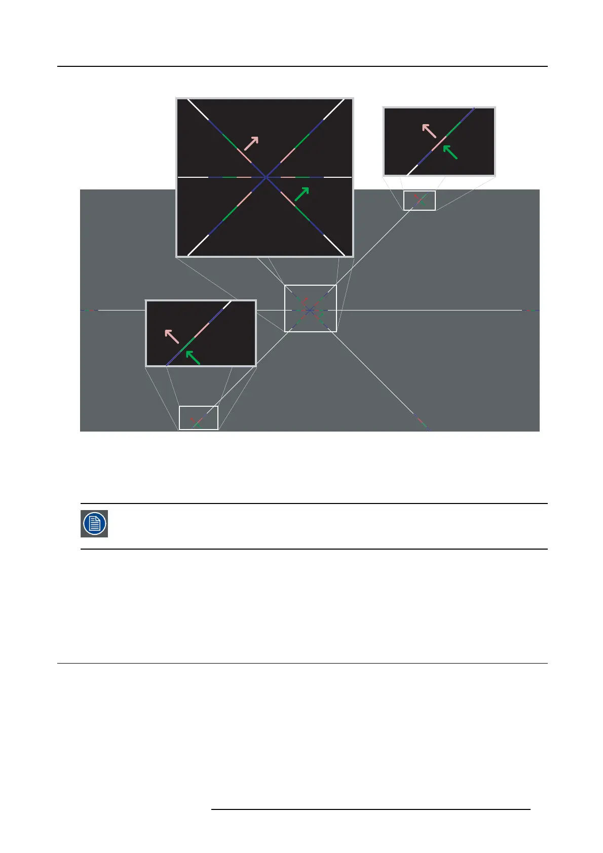
Image 12-3
Convergence test pattern
The test pattern illustrated above is sp ecially designed for convergence purp oses. The test pattern has three red arrows numbered
from 1 to 3 and three green arrows num bered from 4 to 6. T hese numbers and colors correspond w ith the number s and colors of
the extended control k nobs. The direction of the arrow shows the movement of the cha nnel color (red or green) when turning the
corresponding k nob in the direction indicated by the arrow marked on the knob.
The three convergence control knob
s of one chan nel stand in relation with each other. So, a change t o o n e
of them will also effect the adjustment results of the two others. Therefore, all three control knobs have to
be alternately and repeatedly ad justed until the projected color is perfectly converged with the blue reference
color of the test pattern.
Adjustment range
• The adjustment range is limited to approximately 30 pixels in both directions.
• One turn (360°) of a c ontrol knob relates to an approximately 30 pixel displacement on the screen.
• When changing the adjustment d irection there w ill be some play of approximately one turn (360°).
12.2 Preparing the convergence adjustment
Necessary tools
Flat blade screwdriver
Prepare projector for convergence adjustment
1. Remove all side covers and top cover of the projector, see "Removal a nd installation of projector c overs", page 67.
2. Open the sealed c ompartm ent of the light processor, see "Open the sealed compartment", p age 72.
3. Remove the c onvergence cover plate as follow:
R5905050 DP2K C-SERIES 10/07/2012
89
 Loading...


