79R5905752 /16 DP2K C
6.8 Cinema Controller
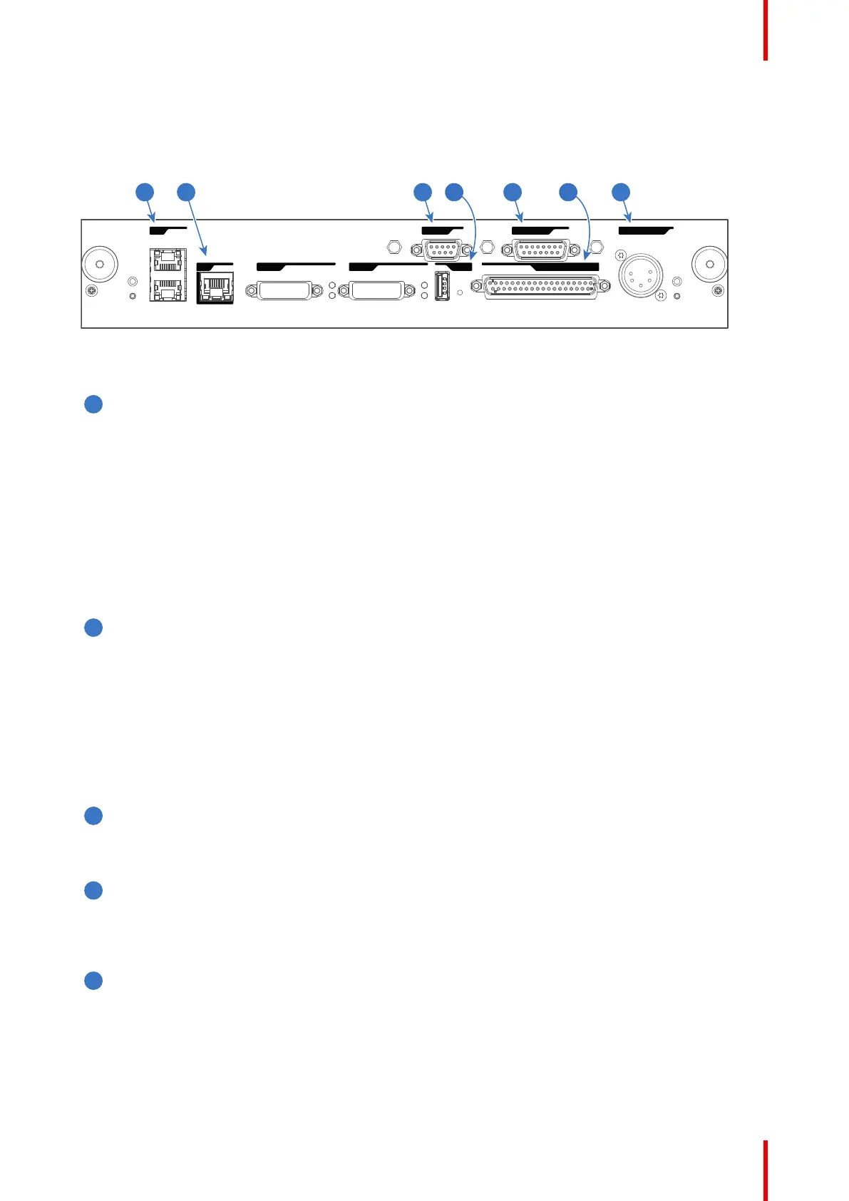
Location of the communication ports
PERIPHERAL PORT
WAN
LAN
GENERAL INTERFACE I/0USB 2.0DVI IN A
DVI IN B
RS 232 IN 3D INTERFACE
1 3 5 72 64
Image 6–8
Functionality
Local Area Network (LAN: 10/100/1000 base-T) port
Local Area Network (LAN: 10/100/1000 base-T) with built-in Ethernet switch (port 1 and port 2). Use for
projector control and automation. E.g. Touch Panel, content server, ... (not for content streaming!)
As there is a need to daisy chain projectors when they are on an Ethernet network, an Ethernet switch is
built in. the incoming network is hereby available for the internal PC and for the next device in the chain.
In this way a 'star' network interconnection can be avoided. The switch used is a stand alone 10/100/
1000Mbit Ethernet switch. This assures no influence on the network speed. Furthermore, this Ethernet
switch remains operational when the projector is in Standby mode.
The connectors used for these Ethernet ports are of the type RJ45, which is compatible with standard
RJ45 cable connector. Straight (most common) as well as cross linked network cables can be used. The
2 ports are functionally identical. Both ports are connected via the projector switch (Auto sensing
enabled).
Wide Area Network (WAN) port
Wide Area Network (WAN: 10/100/1000 base-T). Use this Ethernet port (reference 2 Image 6–8) to
connect the network which contains the DHCP server.
The projector can be connected to a WAN (Wide area network) (reference 2 Image 6–8). Once
connected to the WAN, users can access the projector from any location, inside or outside (if allowed)
their company network using the Communicator software. This software locates the projector on the
network if there is a DHCP server or the user can insert the correct IP-address to access the projector.
Once accessed, it is possible to check and manipulate all the projector settings. Remote diagnostics,
control and monitoring of the projector can then become a daily and very simple operation. The network
connectivity allows detection of potential errors and consequently improves service time.
RS232 IN port
This female DB-9 connector allows you to use a standard serial cable up to 10 meter to connect the
touch panel interface with the projector. Note that the RS232 protocol is used on this connection.
USB OUT port
The Cinema Controller is equipped with a USB port, type “A” connector, (reference 4 Image 6–8) which
can be used to power handheld devices within USB spec (MAX 500mA/5V]. No other functionality
supported (Future expansion). The USB OUT port remains operational in Standby mode.
3D INTERFACE port
3D interface port (reference 5 Image 6–8. Can be used to connect external 3D devices to the projector.
All signals necessary for 3D projection can be provided via this connector. The 3D interface port is
disabled if the projector is in Standby mode.
Input & communication

 Loading...


