R5910599 /00 MDSC-8427 7
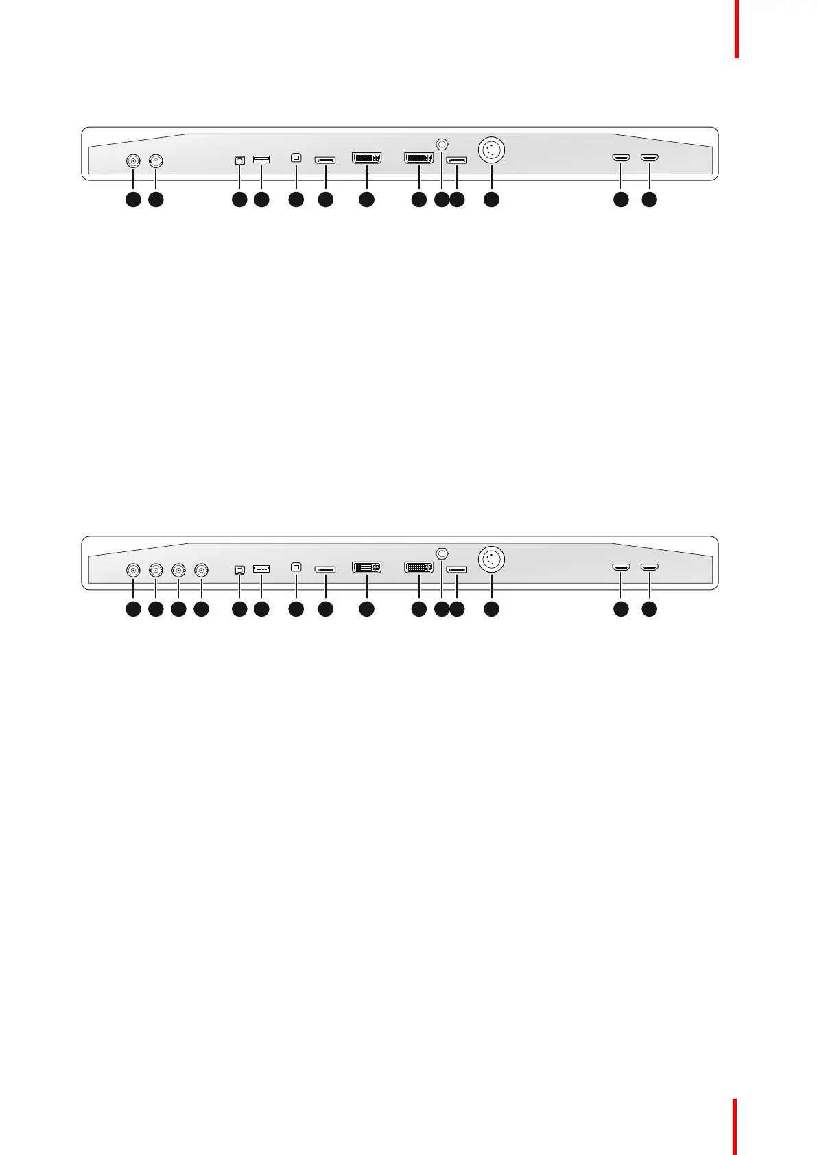
Connections – MDSC-8427 LED version
1 2 3 4 5 6 7 8 9 10 11 12 13
Image 1-2
1. SDI in
2. SDI out
3. +5 VDC – 2 A power out
4. USB 2.0 type A interface
5. USB 2.0 type B interface
6. Main (Right) DisplayPort in
7. DVI-D in
8. DVI-D out
9. Potential Equalization pin (POAG)
10.2
nd
(Left) DisplayPort in
11. VDC in
12.HDMI 2 in
13.HDMI 1 in
Connections – MDSC-8427 12G version
1 2 3 4 5 6 7 8 9 10 11 12 13 14 15
Image 1-3
1. SDI 1: 12G-SDI in or Quad-SDI in top left
(*)
2. SDI 2: 12G-SDI out or Quad-SDI in top right
(*)
3. SDI 3: 12G-SDI in or Quad-SDI in bottom right or 3G-SDI 2nd input
(*)
4. SDI 4: 12G-SDI out or Quad-SDI in bottom left
(*)
5. +5 VDC – 2 A power out
6. USB 2.0 type A interface
7. USB 2.0 type B interface
8. Main (Right) DisplayPort in
9. DVI-D in
10.DVI-D out
11. Potential Equalization pin (POAG)
12.2
nd
(Left) DisplayPort in
13.VDC in
14.HDMI 2 in
15.HDMI 1 in
(*)
See “SDI config”, page 29 for details on how to configure 12G-SDI & Quad-SDI.
Welcome!
 Loading...