56-101-01501_01502 Revision D Page | viii
LIST OF FIGURES
PAGE
Figure 1 Identification Label ..................................................................................................... ix
Figure 2 Owner Warranty Registration Card .............................................................................. x
Figure 3 Limited Warranty ....................................................................................................... xii
Figure 4 Case Dimensions ....................................................................................................... 5
Figure 5 Battery Holders .......................................................................................................... 6
Figure 6 28VDC Connection ..................................................................................................... 7
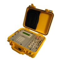
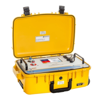
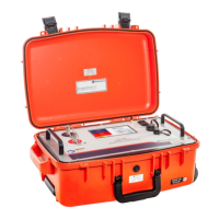
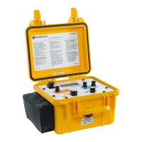
Figure 7 DFQ40K Front Panel and Function Switches ............................................................... 8
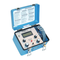
Figure 8 DFQ40K Display ......................................................................................................... 9
Figure 9 Instruction Manual, P/N 56-101-01501_1502 ............................................................10
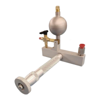
Figure 10 Accessory Lead Package P/N 101-01511 ...............................................................11
Figure 11 6 each Alkaline C Cell Batteries ..............................................................................11
Figure 12 28 VDC Power Cable ..............................................................................................11
Figure 13 Correct Battery Orientation ......................................................................................12
Figure 14 Main Menu Screen ..................................................................................................13
Figure 15 Aircraft Insulation Test Configuration .........................................................................15
Figure 16 Aircraft Capacitance Test Configuration ....................................................................17
Figure 17 Aircraft Indicator Test Configuration .........................................................................19
Figure 18 Aircraft Preferred Calibration Configuration ................................................................21
Figure 19 Aircraft Preferred Calibration Configuration ...............................................................23
Figure 20 Bench Insulation Test Configuration .........................................................................25
Figure 21 Bench Capacitance Test Configuration ....................................................................27
Figure A1 Display Navigation Guide .........................................................................................32
Figure A2 Setting Navigation Guide .........................................................................................33
LIST OF TABLES
PAGE
Table 1 Physical Characteristics ............................................................................................... 1
Table 2 Environmental .............................................................................................................. 1
Table 3 Specifications ............................................................................................................... 2
Table 4 Display Units ................................................................................................................ 2
Table 5 Environmental .............................................................................................................. 4