AW00123401000 Physical Interface
Basler ace USB 3.0 27
5 Physical Interface
This chapter provides detailed information, such as pinouts and voltage requirements, for the
physical interface on the camera. This information will be especially useful during your initial
design-in process.
5.1 General Description of the
Camera Connections
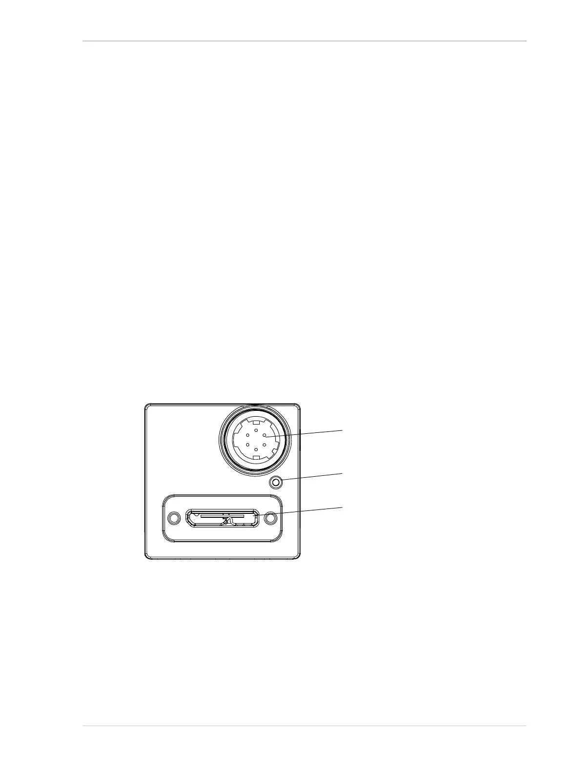
The camera is interfaced to external circuity via connectors located on the back of the housing:
A 6-pin connector used to provide access to the camera’s I/O lines
A USB 3.0 Micro-B port used to provide a (nominal) 5 Gbit/s SuperSpeed connection to the
camera.
There is also a LED indicator located on the back of the camera.
Figure 15 shows the location of the two connectors and the LED.
Fig. 15: Camera Connectors
USB 3.0 Micro-B Port
6-pin Connector (I/O)
Green LED Indicator