Physical Interface AW00123401000
40 Basler ace USB 3.0
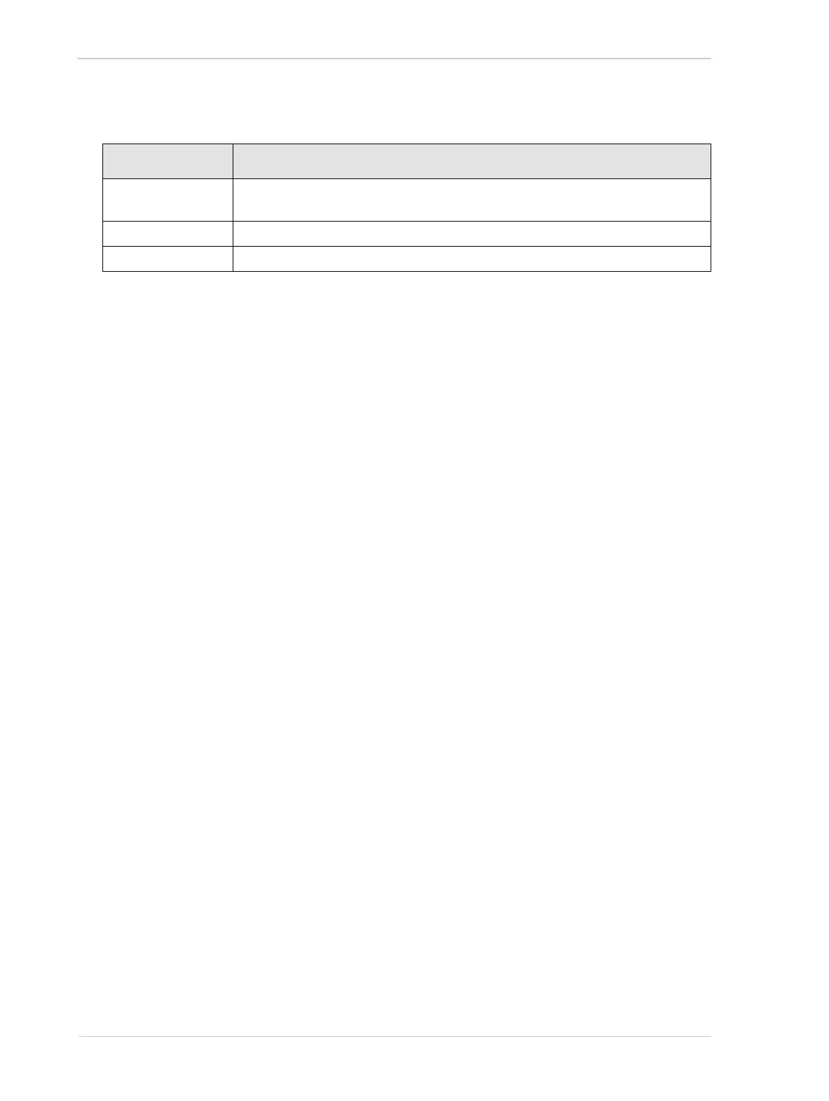
The following voltage requirements apply to a direct-coupled GPIO line when it is set as an
output and when it is in the "off" state:
The following applies to a direct-coupled GPIO line when it s set as an output and when it is in
the "on" state:
Use a pull up resistor to account for the fact that the camera uses an open collector GPIO
output. The residual voltage will typically be approximately 0.4 V at 50 mA and 25 °C housing
temperature.
The actual residual voltage, however, depends on camera operating temperature, load current,
and production spread.
Note: The maximum current allowed through the output circuit is 50 mA.
5.9.4.2 Electrical Characteristics
As shown in Figure 22, shows the applicable electrical circuit when a GPIO line is set to operate as
an output. The figure is drawn to specifically apply to pin 1 (Line 3) as an example but, with the
necessary modifications, it equally applies to pin 3 (Line 4).
Voltage Significance
+30.0 VDC Absolute maximum; the camera can be damaged if the absolute maximum is
exceeded.
+3.3 to +24 VDC Recommended direct-coupled GPIO output supply voltage range.
< +3.3 VDC The direct-coupled GPIO output can operate erratically.
Table 7: Voltage Requirements for a Direct-coupled GPIO Line Set as an Output