Physical Interface AW00123401000
28 Basler ace USB 3.0
5.2 Camera Connector Pin Numbering and
Assignments
5.2.1 6-pin Connector Pin Numbering and
Assignments
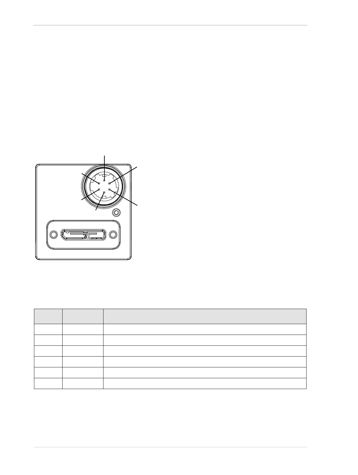
The 6-pin connector is used to access the physical input and output lines on the camera.
The pin numbering for the 6-pin connector is as shown in Figure 16.
The pin assignments and designations for the 6-pin connector are shown in Table 3.
.
Pin Designation Function
1 Line 3 Direct-coupled General Purpose I/O (GPIO)
2 Line 1 Opto-isolated I/O IN
3 Line 4 Direct-coupled General Purpose I/O (GPIO)
4 Line 2 Opto-isolated I/O OUT
5 - Ground for opto-isolated I/O
6 - Ground for direct-coupled GPIO
Table 3: Pin Assignments for the 6-pin Connector and Related Designations
Fig. 16: Pin Numbering for the 6-pin Connector
4
3
5
6
1
2