AW00123401000 Physical Interface
Basler ace USB 3.0 35
5.8.2 Electrical Characteristics
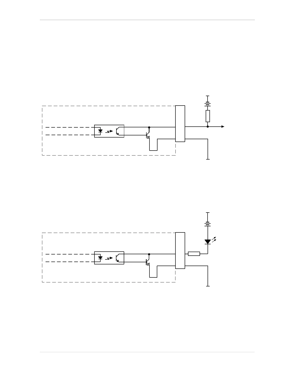
Figure 18 shows a schematic for the opto-isolated output line. See the previous section for
recommended voltages and their significances. The absolute maximum voltage is +30.0 VDC.
The maximum current allowed through the output circuit is 50 mA.
Figure 18 shows a typical external circuit you can use to monitor the output line with a voltage signal
.
Figure 19 shows a typical circuit you can use to monitor the output line with an LED or an
pto-coupler. In this example, the voltage for the external circuit is +24 VDC. Current in the circuit
is limited by an external resistor.
For more information about output line pin assignments and pin numbering, see Section 5.2 on
page 28.
For more information about the Exposure Active signal, see a following version of the manual.
Your
Gnd
Your
Gnd
+3.3 to +24
VDC
Camera
Voltage
Output
Signal
to You
Q1
1
6
3
4
2
5
Fig. 18: Opto-isolated Output Line Schematic with a Typical Voltage Output Circuit (Simplified)
Your
Gnd
Camera
Q1
1
6
3
4
2
5
Your Gnd
LED
Output
to You
+24
VDC
2.2k
Fig. 19: Opto-isolated Output Line Schematic with a Typical LED Output Signal at +24 VDC for the External Circuit
(Simplified)