AW00123401000 Physical Interface
Basler ace USB 3.0 41
For more information about GPIO pin assignments and pin numbering, see Section 5.2.1 on
page 28.
For more information about setting the GPIO line operation, see a following version of the manual.
5.9.4.3 Selecting a Source Signal for the Output Line
When a GPIO line is configured to act as an output line, you must select a source signal for the line
to make the line useful. The camera has several standard output signals available and any one of
them can be selected to act as the source signal for the output line.
For more information about selecting a source signal for the output line, see a following version of
the manual.
6-pin
Receptacle
1
6
3
4
2
5
FPGA Output
+3.3 VDC
(Typical)
Pull Up Resistor
Camera
Your
Gnd
+3.3 to +24
VDC
Voltage
Output
Signal
to You
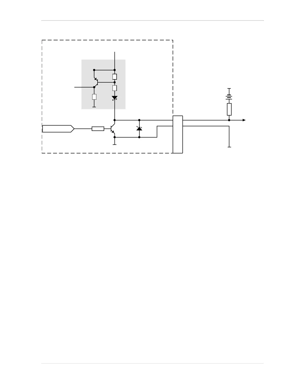
Fig. 22: Direct-coupled GPIO Line Schematic with the GPIO Line Set as an Output and with a Typical Voltage
Output Circuit (Illustration for Pin 1 as an Example; Simplified)