AW00123401000 Physical Interface
Basler ace USB 3.0 37
5.9.2 Operation as an Input
This section describes the electrical operation of a GPIO line when the line has been set to operate
as an input.
5.9.2.1 Voltage Requirements
The following requirements apply to a direct-coupled GPIO line when the line is set as an input.
Your application must be able to accept 2 mA (sink current) from the direct-coupled GPIO input line
without exceeding +0.8 VDC, the upper limit of the low state.
5.9.2.2 Electrical Characteristics
Figure 20 shows the applicable electrical circuit when a GPIO line is set to operate as an input. The
figure is drawn to specifically apply to pin 1 (Line 3) as an example. However, with the necessary
modifications, the figure applies equally to pin 3 (Line 4).
The figure shows, as an example, the use of a TTL or CMOS logic gate in the external circuit. A
different example for an external circuit is shown in Figure 21.
See the previous section for input voltages and their significances. The current draw for each input
line is between 5 mA and 15 mA.
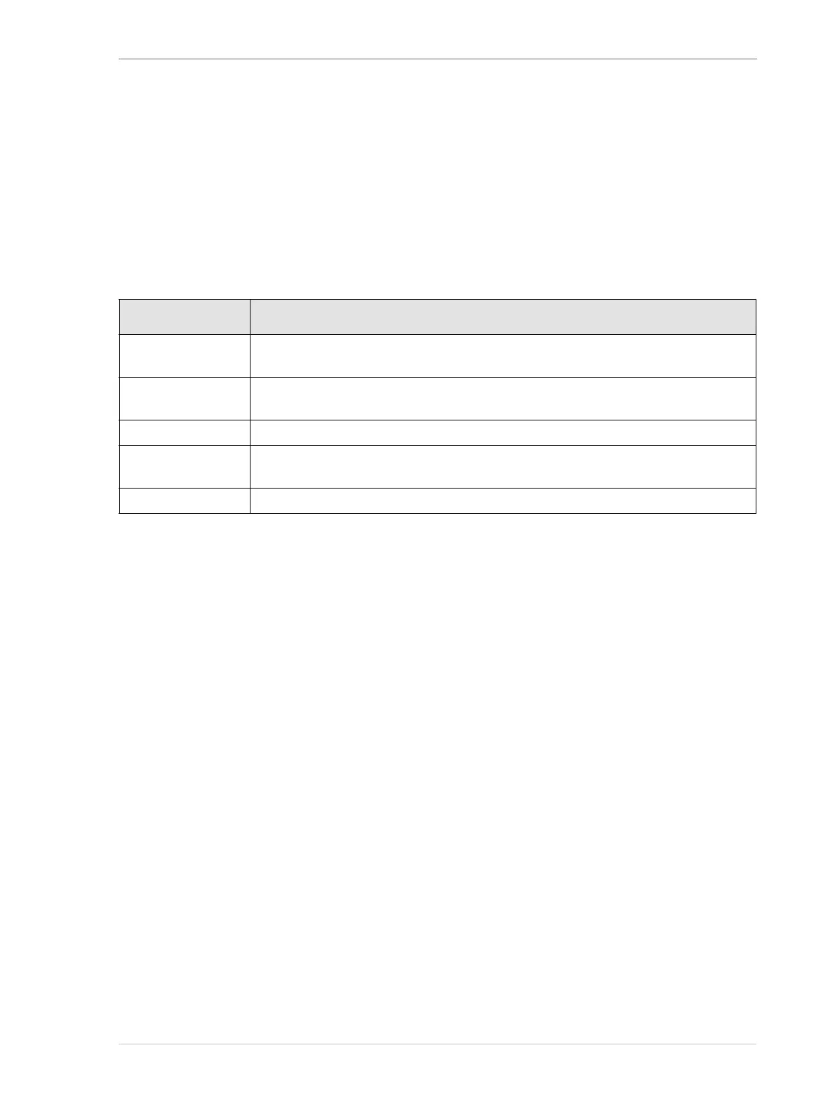
Voltage Significance
+30.0 VDC Absolute maximum; the camera can be damaged when the absolute maximum is
exceeded.
+0 to + 5.0 VDC Recommended input voltage range (the minimum external pull up voltage is 3.3 VDC as
illustrated in Figure 21).
+0 to +0.8 VDC The voltage indicates a logical 0.
> +0.8 to +2.0 VDC Region where the transition threshold occurs; the logical state is not defined in this
region.
> +2.0 VDC The voltage indicates a logical 1.
Table 6: Voltage Requirements for a Direct-coupled GPIO Line Set as an Input