9492600990 6-1
DECS-150 Auxiliary Control
6 • Auxiliary Control
BESTCOMSPlus Navigation Path: Settings Explorer, Operating Settings, Auxiliary Input
The DECS-150 accepts an external analog control signal for auxiliary control of the regulation setpoint.
Auxiliary setpoint control is possible in all regulation modes: AVR, PF, Var, and FCR. The control signal
can also be used for power system stabilizer control.
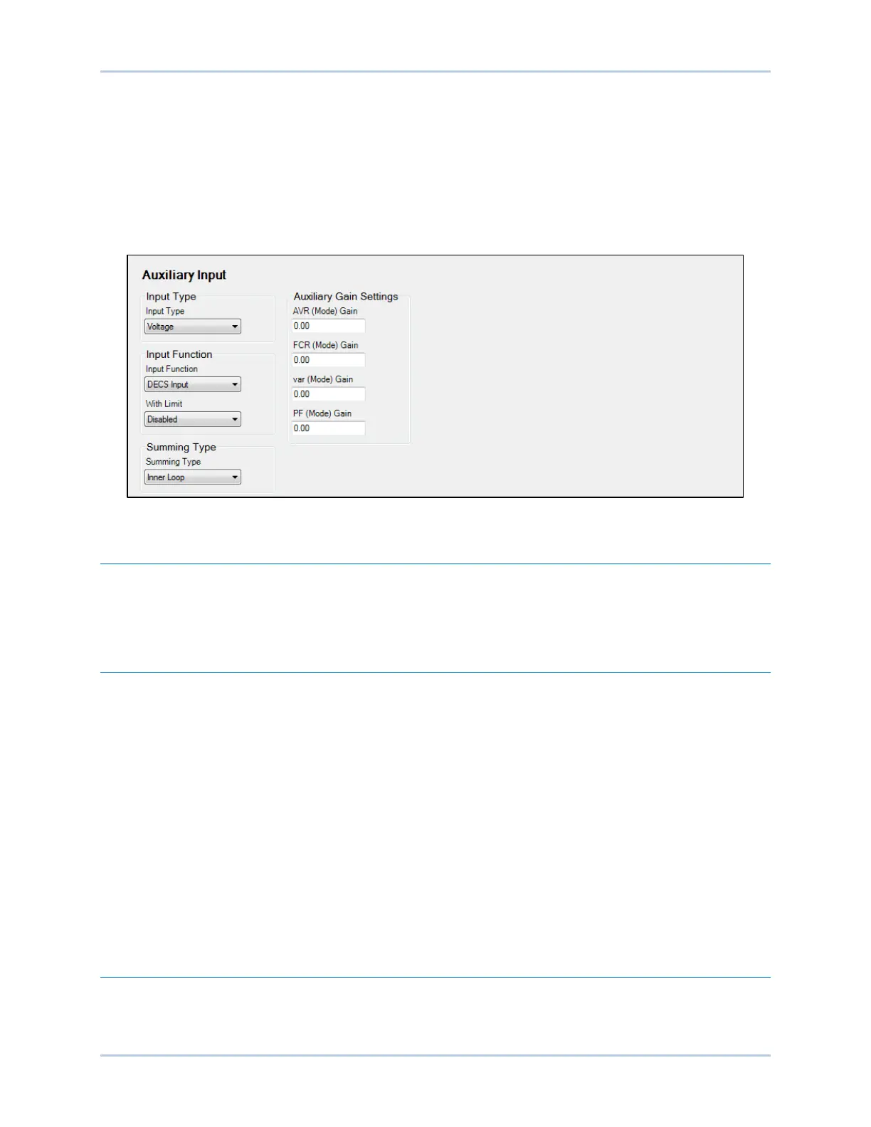
The Auxiliary Input screen is illustrated in Figure 6-1.
Figure 6-1. Auxiliary Input Screen
Auxiliary Control Input Type
Either a voltage or current control signal may be used for auxiliary control. Terminals I+ and I– accept a 4
to 20 mAdc signal. Terminals V+ and V– accept a –10 to +10 Vdc signal. The input type is selected in
BESTCOMSPlus
®
.
Auxiliary Control Input Function
The analog control input can be used for auxiliary control of the regulation setpoint, as a power system
stabilizer test input, or for grid code input.
PSS Test Input
The auxiliary control input can be used for control of the optional power system stabilizer function during
testing and validation. More information is provided in the Power System Stabilizer section.
Grid Code Input
The grid code input must be selected when it is desired to use the auxiliary input as the adjustment
source for active and reactive power control.
Setpoint Limits
Minimum and maximum setpoint limits are observed when the With Limit box is checked.
Auxiliary Control Gains
When a current input type is selected, the input current is converted internally by the DECS-150 into a
voltage signal in the range of –10 to +10 Vdc. The DECS-150 uses Equation 6-1 when converting the
applied current into a voltage.