9492600990 4-1
DECS-150 Voltage and Current Sensing
4 • Voltage and Current Sensing
The DECS-150 senses machine voltage, machine current, and bus voltage through dedicated, isolated
inputs.
Machine Voltage
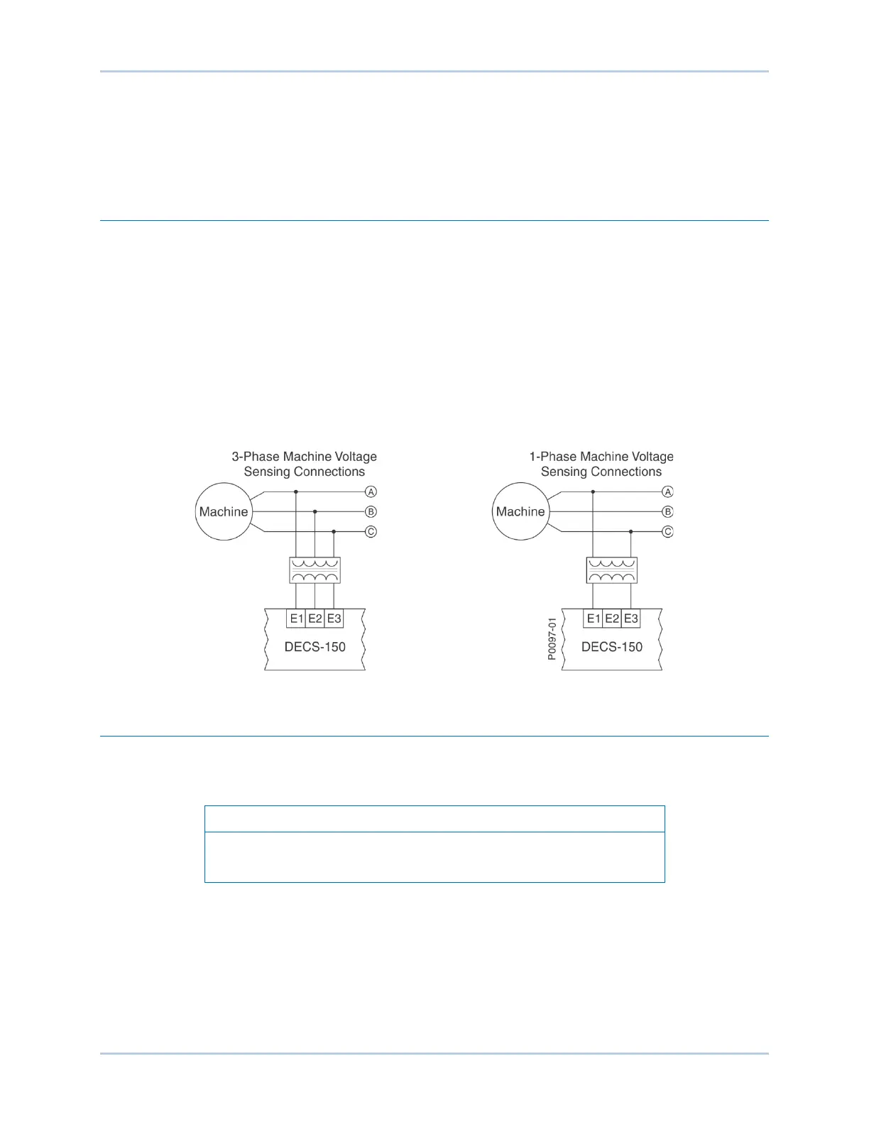
Three-phase machine sensing voltage is applied to DECS-150 terminals E1, E2, and E3. This sensing
voltage is typically applied through a user-supplied voltage transformer, but may be applied directly.
These terminals accept three-phase, three-wire connections at terminals E1 (A), E2 (B), and E3 (C) or
single-phase connections at E1 (A) and E3 (C).
The machine voltage sensing input accepts a maximum voltage of 600 Vac and has a burden of less than
1 VA.
The transformer primary and secondary winding voltages are entered in settings that the DECS-150 uses
to interpret the applied sensing voltage and calculate system parameters. The phase rotation of the
machine sensing voltage can be configured as ABC or ACB. Information about configuring the DECS-150
for the machine sensing voltage is provided in the Configuratio n section.
Typical machine voltage sensing connections are illustrated in Figure 4-1.
Figure 4-1. Typical Machine Voltage Sensing Connections
Machine Current
Machine current sensing inputs consist of three phase-sensing inputs and a sensing input for cross-
current compensation.
Current transformer (CT) grounding should be applied in accordance
with local codes and conventions.
Phase Sensing
Three-phase machine sensing current is applied to DECS-150 terminals IA+ and IA–, IB+ and IB–, and
IC+ and IC– through user-supplied current transformers (CTs). Single-phase machine sensing current is
applied to DECS-150 terminals IB+ and IB–. The DECS-150 is compatible with CTs having 5 Aac or 1
Aac nominal secondary ratings. The DECS-150 uses this secondary rating, along with the CT nominal
primary ratings to interpret the sensed current and calculate system parameters. Information about
configuring the DECS-150 for the machine sensing voltage is provided in the Configuration section of this
manual. Typical machine phase-current sensing connections are shown in Figure 4-2.