8-2 9492600990
Protection DECS-150
Block Logic Input
The Block input provides logic-supervision control of the element. When true, the Block input disables the
element and resets the timer. Connect the element Block input to the desired logic in BESTlogicPlus.
Machine Overvoltage
An overvoltage pickup condition occurs when any phase of the sensed machine terminal voltage
increases above the Pickup setting. An overvoltage trip condition occurs if the machine voltage remains
above the pickup threshold for the duration of the Time Delay setting. Machine overvoltage protection can
be enabled and disabled without altering the pickup and time delay settings. Overvoltage pickup and trip
elements in BESTlogicPlus can be used in a logic scheme to initiate corrective action in response to the
condition.
Settings that are related to machine ratings can be set in either actual units of voltage or in per unit
values. When a native unit is edited, BESTCOMSPlus automatically recalculates the per unit value based
on the native unit setting and the rated data parameter (on the System Parameters, Rated Data screen)
associated with it. When a per unit value is edited, BESTCOMSPlus automatically recalculates the native
value based on the per unit setting and the rated data parameter associated with it.
Once all per unit values are assigned, if the rated data parameters are changed, BESTCOMSPlus
automatically recalculates all native unit settings based on the modified rated data parameters.
The Overvoltage pickup has a native unit of Primary Volts and the rated data associated with it is
Machine Rated Data, Voltage (on the System Parameters, Rated Data screen).
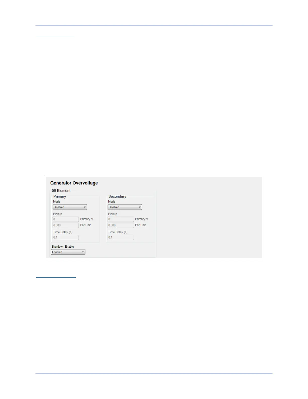
The Generator Overvoltage screen is illustrated in Figure 8-2. The Motor Overvoltage screen is similar.
Figure 8-2. Generator Overvoltage Protection Settings
Shutdown Enable
When checked, Shutdown Enable causes the DECS-150 to stop excitation when the machine
overvoltage element trips.
Loss of Sensing
The machine voltage is monitored for a loss of sensing (LOS) condition.
In the DECS-150, a loss of sensing event is calculated using sequence components. A loss of sensing
event occurs when the positive sequence voltage (V1) drops below the Voltage Balanced Level setting of
the AVR setpoint, or when the negative sequence voltage (V2) increases above the Voltage Unbalanced
Level setting of the positive sequence voltage. A time delay is started when the event occurs, delaying
the alarm by a predetermined time.
A loss of sensing condition can be used to initiate transfer to manual (FCR) control mode. It also can be
configured in BESTlogicPlus to initiate other actions. Protection can be enabled and disabled without
altering the individual loss of sensing settings.