10-14 9492600990
Grid Code DECS-150
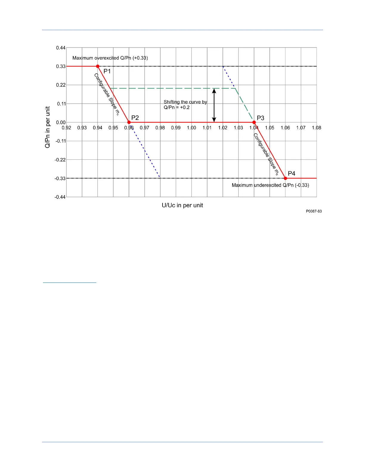
Figure 10-15. Q(Voltage Limit) Curve Example
The reactive power value (Qref/Pb inst) can be adjusted in steps of 1% (Pb inst) but the range of the
characteristic curve between P2 and P3 must take into account the gradients m
A
and m
B
. The parameter
may be modified by a setting change or through remote communication. The network operator
determines the availability of remote setpoint adjustment in the planning phase.
After modification of the value (Qref/Pb inst), the machine output must achieve the specified output level
within a maximum of four minutes.
Adjustment Sources
The Q(Voltage Limit) setpoint may be adjusted by the DECS-150 auxiliary input or via remote
communication (Modbus
®
). For all adjustment sources, the value of the Q(Voltage Limit) Gain setting is
applied to the value read from the selected input. Refer to the Modbus Communication section for more
information on adjusting the setpoint via remote communication.
Auxiliary Input
To use the DECS-150 auxiliary input as the Q(Voltage Limit) adjustment source, make the following
settings:
• On the Auxiliary Input screen, set the Input Function setting to Grid Code Input. Refer to the
Auxiliary Control section for details.
• On the Active Power Control screen, set the Adjust Source setting to Auxiliary Input.
Refer to the Auxiliary Control section for details on how the auxiliary voltage (Vaux) is calculated.
Vaux is multiplied by 0.01 and the value of the Q(Voltage Limit) Gain setting:
(APC Adjust = Vaux x 0.01 x Q(Voltage Limit) Gain).