9492600990 10-13
DECS-150 Grid Code
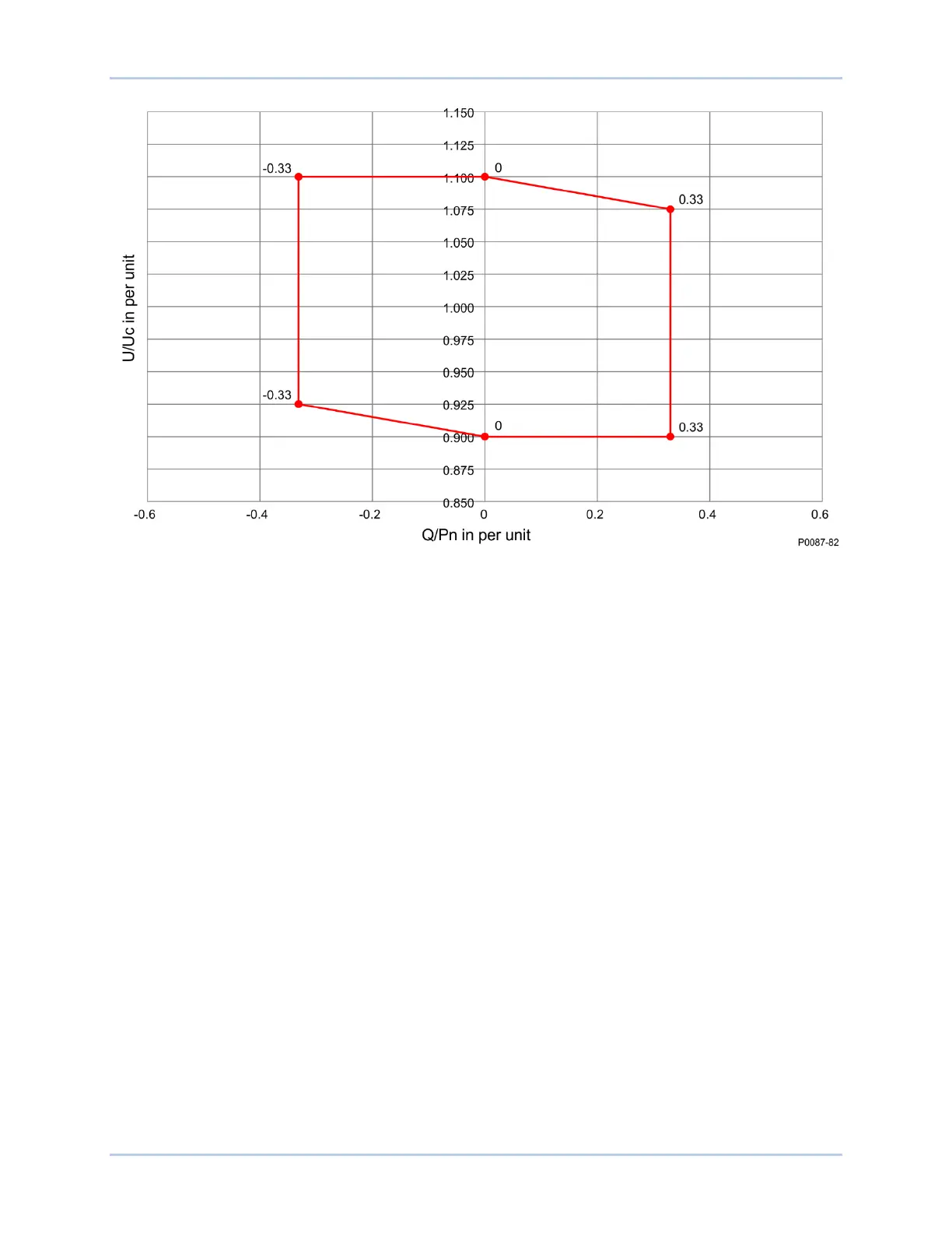
Figure 10-14. Q(Voltage Limit) Voltage Dependent Provision of Reactive Power
The characteristic curve consists of four points (denoted P1, P2, P3, and P4) with coordinates of per unit
voltage and per unit reactive power. The points and slopes of the characteristic are as follows:
P1: (Up1/Uc; Qp1/Pbinst)
P2: (Up2/Uc ; Qref/Pbinst)
The slope of the characteristic curve section m
A
= (Qp1/Pbinst – Qref/Pbinst) / (Up1/Uc – Up2/Uc);
P3: (Up3/Uc ; Qref/Pbinst),
P4: (Up4/Uc ; Qp4/Pbinst)
The slope of the characteristic curve section m
B
= (Qref/Pbinst – Qp4/Pbinst) / (Up3/Uc – Up2/Uc);
To help ensure stability, gradients greater than m=24 are not permitted.
The network operator specifies the four points when the installation is planned. Unless specified by the
network operator, the following value pairs apply:
P1 (0.94; 0.33), P2 (0.96;0), P3( 1.04; 0), P4 (1.06, -0.33)
An example characteristic is shown in Figure 10-15.