13-10 9440300990
Metering DECS-250
AEM-2020 Inputs
Status annunciations for the optional AEM-2020 Analog Expansion Module’s analog, RTD, thermocouple,
and analog metering inputs are provided on the BESTCOMSPlus remote analog inputs, remote RTD
inputs, remote thermocouple inputs, and remote analog input values screens. These screens are
described and illustrated in the Analog Expansion Module chapter of this manual.
Outputs
BESTCOMSPlus Navigation Path: Metering Explorer, Status, Outputs
HMI Navigation Path: Metering Explorer, Status, Outputs
Status annunciation is provided for the DECS-250 contact outputs and optional Contact Expansion
Module (CEM-2020) contact outputs. Annunciation is also provided for the optional Analog Expansion
Module (AEM-2020) analog outputs.
DECS-250 Contact Outputs
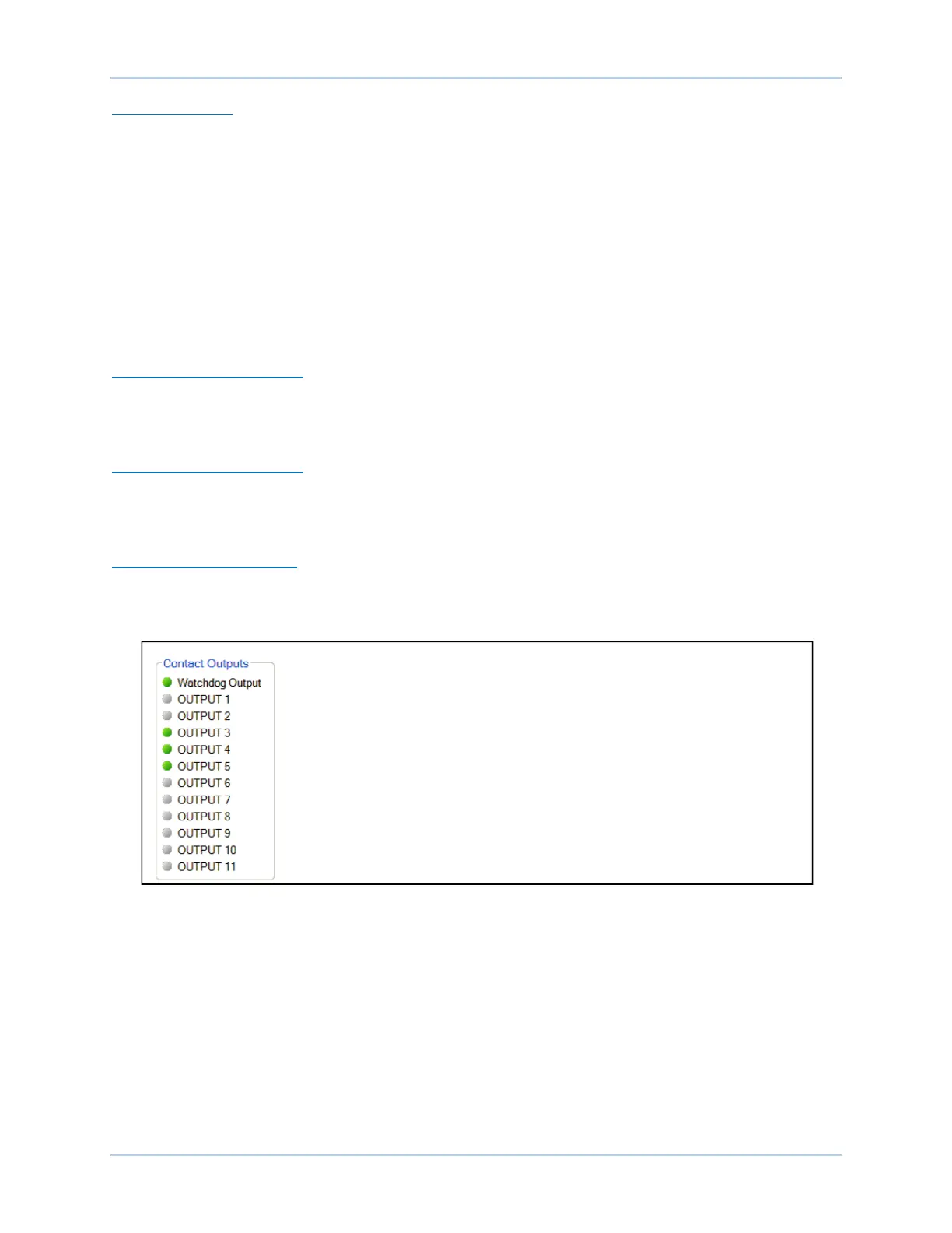
Status indication for the DECS-250’s Watchdog and 11 contact outputs is provided on the
BESTCOMSPlus contact outputs screen illustrated in Figure 13-15. An indicator changes from gray to
green when the corresponding output changes state (Watchdog output) or closes (Output 1 through 11).
CEM-2020 Contact Outputs
The status of the 24 contact outputs of the optional CEM-2020 Contact Expansion Module is provided on
the BESTCOMSPlus remote contact inputs screen. See the Contact Expansion Module chapter of this
manual for a description and illustration of this screen.
AEM-2020 Analog Outputs
Metering and status indications provided by the optional AEM-2020 Analog Expansion Module are shown
on the BESTCOMSPlus remote analog outputs screen. This screen is described and illustrated in the
Analog Expansion Module chapter of this manual.
Figure 13-15. DECS-250 Contact Outputs Status Indication Screen
Network Load Share
The screen shown in Figure 13-16 reports the error percent, reactive current, NLS average reactive
current, and number of generators online. The status indicators change from gray to green when a status
is active.
The Error percent is the deviation of the unit’s reactive current from the system average. The NLS
Average Reactive Current is the average of the reactive current of every unit in the system. Generators
Online is the number of units actively load sharing.