3 | Description Baumer
10 Operating Manual OM20/ OM30 RS485 with Modbus RTU | V1
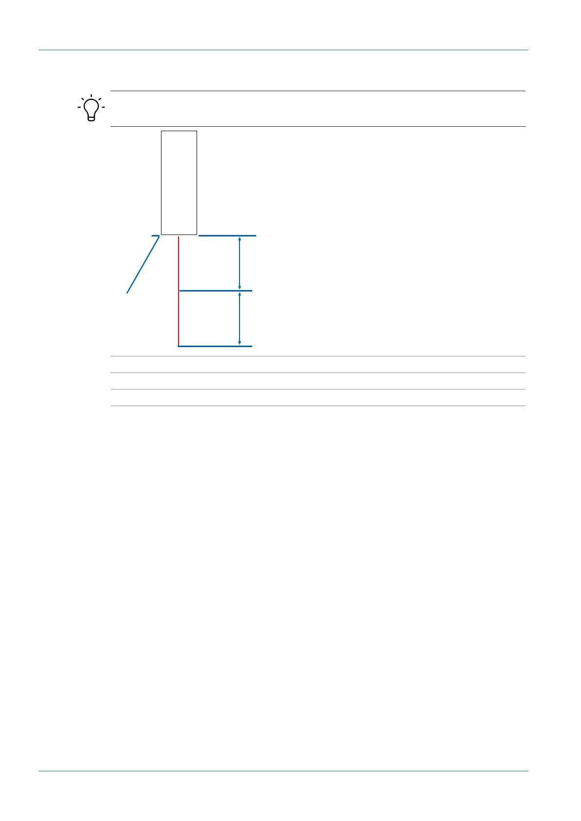
3.3 Measurement field
INFO
The data for your sensor version can be found in the data sheet.
ZP Zero position CD Blind region
Sdc Start of the measurement range MR Measurement range
Sde End of the measurement range
Blind region (CD)
n
Region in which the sensor cannot detect any measurement objects.
n
Unwanted objects (objects not to be measured) in this region may lead to deviations in the
measurement results.
Measuring range (MR)
n
Region in which the measurement object must be present for the sensor to deliver reliable
measurement results.
n
Unwanted objects (objects not to be measured) in this region may lead to deviations in the
measurement results.
n
The limits of the measurement range (MR) are defined via the parameters Start of the mea-
surement range (Sdc) and End of the measurement range (Sde).
Zero position (ZP)
n
In the factory settings, the zero point is located on the front of the sensor (ZP=0mm). The
output consists of the distance between the front of the sensor and the object to be mea-
sured.
n
The following values depend on the zero position:
▪ Output measured values
▪ Switching points
n
Capable of parameterization via:
▪ Modbus RTU
▪ Teach button