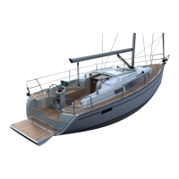
Systems(someareoptionalonly)
29
6.4.7. TheDCsystemconsistsofthefollowingcircuits/consumers
Pos. Description
1 TV
2 el. anchor windlass
3 Controlsanchorwindlass/socket
4 Sensor fresh water
5 Multisensor(Log-Echosounder)
6 iPod- Station
7 Consumer batteries
8 Mainswitchconsumers/bowthruster
9 Fresh water pump
10 Shower sump pump
11 El.bilgepump(alsosump)
12 El. bilge pump
13 Starter battery engine
14 Battery charger
15 Electricalpanels12V
16 Mainswitchengine/generator
17 AutopilotEVCGarmin(Option)
18 KompassAutopilot(Option)
19 BatteryBowandsternthrusters(Option)
20 MotorAutopilot(Option)
21 Engine Starter
22 Rectier
23 Sensor diesel tank
24 Boiler
27 Refrigeration plant
28 Shoreconnection230/110V(Deck)
32 Through deck cable conduit
33 Loudspeaker
34 Radio
Pos. Description
35 AntennaRadio
36 Engine panel
37 Fuel gauge
38 DisplayGarminGMI10
40 GarminGHP12
41 Compass
42 Bow-/sternthruster(Option)
43 Controlunitbowthruster(Option)*1
44 ControlunitRevo-winch(Jib)/engine
45 Electr.jibwinchdrive(Option)
46 Heater(Option)
47 Dieselpumpheater(Option)
48 Thermostatheater(Option)
49 Sensorheating(Option)
51 Sensor black water tank
52 Fusesanchorwindlass/e-Winches(Option)
53 Fuses consumer Heating (30A), auto pilot
(30A),bowthruster*1
54 Chart plotter
55 GPS-Antenna
56 Fuse battery charger
57 Relay anchor windlass
69 Earthing anode
66 Ventilatorengineroom
65 Residualcurrentcircuitbreaker(AftLocker)
61 Microwave
72 Earth engine block
The value of the tripping current of each main knife fuse is marked on the fuse itselfm replace the fuses only with
fusesofequivalentratingandquality.Switchoffthemainswitch,theunitmustbeproperlydisconnectedfromthe
power supply before any work is performed on it.